
Distance measuring system and method of calibrating optical paths of distance measuring system

A distance measuring system and optical path technology, which is applied in the direction of radio wave measurement system, measuring device, electromagnetic wave reradiation, etc., can solve the problems that the distance measurement accuracy of the range finder cannot meet the ideal high precision requirements, diameter error, large size, etc.

Pending Publication Date: 2017-03-15
NORTHWEST INSTR SHANGHAI +1
View PDF0 Cites 1 Cited by
  • Summary
  • Abstract
  • Description
  • Claims
  • Application Information

AI Technical Summary

Problems solved by technology

[0003] In the process of laser ranging, the optical axes of the emitted light and the received light need to be parallel or basically parallel to the mirror group. The ranging accuracy of the range meter is often not up to the ideal high precision requirements
[0004] In addition, as the requirements for portability become higher and higher, the size requirements for the distance measuring system are also higher and higher. Due to the limitation of the structure, the range finder in the prior art is relatively large in size and inconvenient to carry.

Method used


Image

  • Distance measuring system and method of calibrating optical paths of distance measuring system
  • Distance measuring system and method of calibrating optical paths of distance measuring system
  • Distance measuring system and method of calibrating optical paths of distance measuring system

Examples


Embodiment Construction

[0037] The idea, specific structure and technical effects of the present invention will be clearly and completely described below in conjunction with the embodiments and accompanying drawings, so as to fully understand the purpose, features and effects of the present invention.

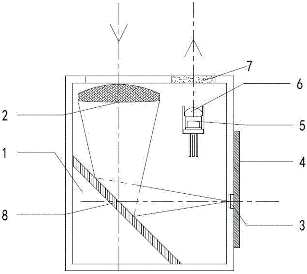
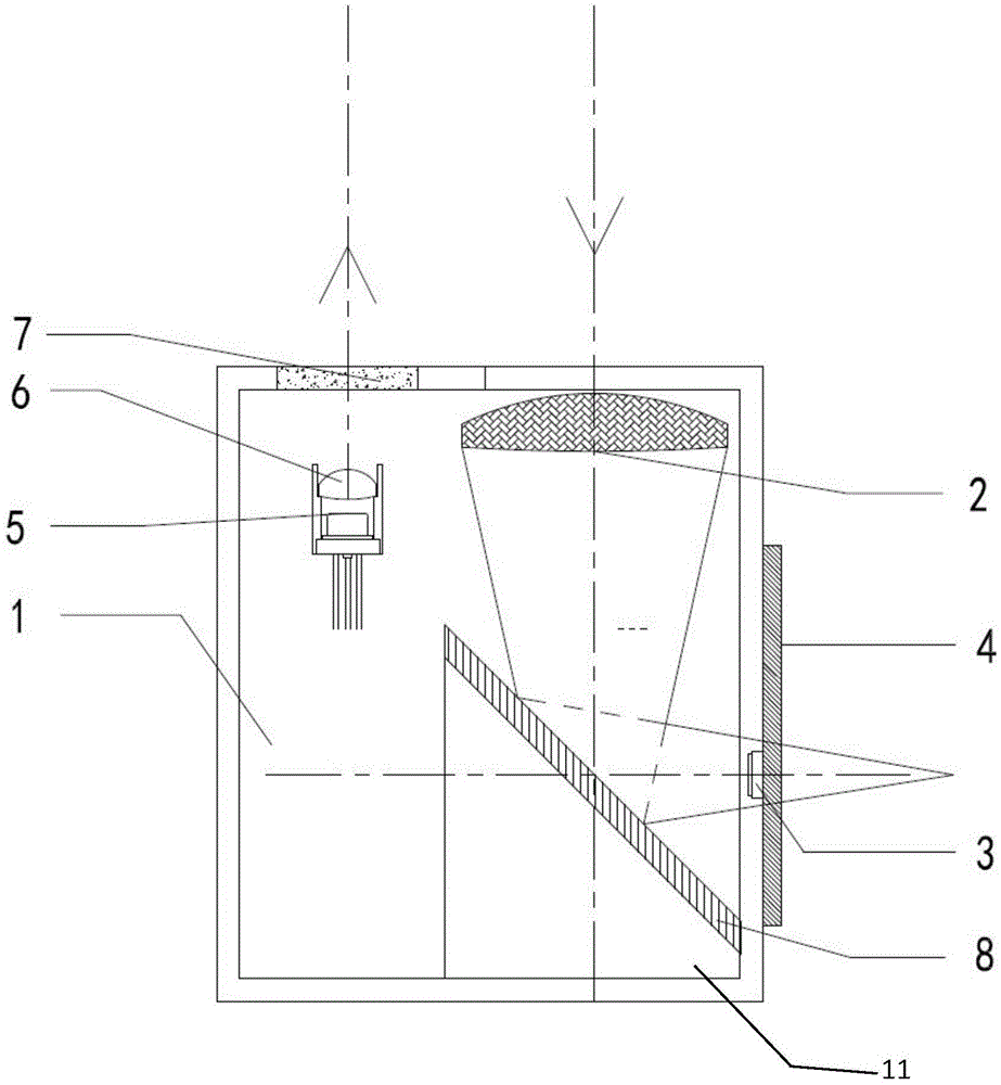
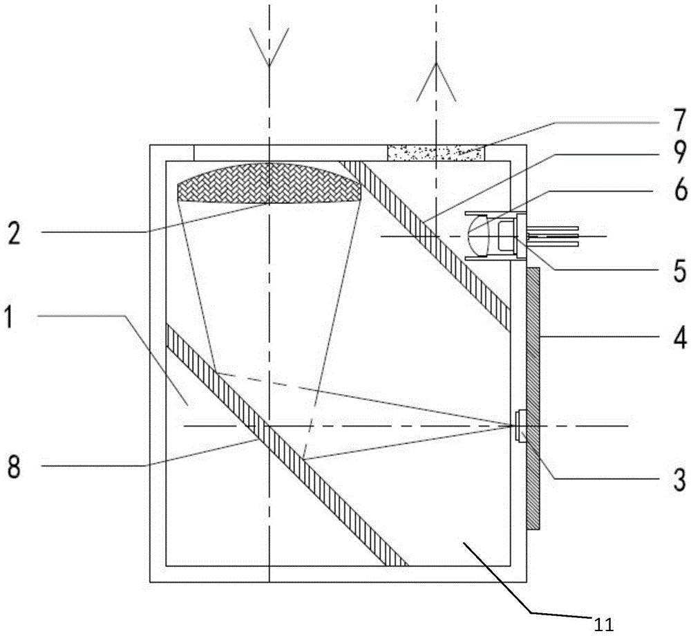
[0038] figure 1 The first embodiment of the distance measuring system of the present invention is shown. The distance measuring system in this embodiment includes an assembly 1, a receiving mirror group 2, a receiving sensor 3, a circuit board 4, a transmitting assembly 5 and a first refracting mirror group 8 , the receiving lens group 2 is fixed on the side part 11 of the assembly 1 through the circuit board 4, the emitting assembly 5 emits a laser beam to form an emitting optical path, and the emitting optical path is emitted to the object to be measured, and then from The object to be measured is reflected to the receiving mirror group 2, and the reflected optical path is refracted by the first ref...


PUM


Abstract

The invention provides a distance measuring system comprising an assembly body, a transmitting assembly, a receiving mirror group, a receiving sensor, and refractor groups. The refractor groups are disposed on the assembly body. The transmitting assembly and / or the receiving sensor are / is disposed on the side part / s of the assembly body. The refractor groups can move in at least one direction, and optical paths are changed by the refraction of the refractor groups, and the miniaturization of the size of the distance measuring system is realized. The invention also provides a method of calibrating the optical paths of the distance measuring system. By moving a first refractor group and a second refractor group to adjust and calibrate the optical paths, a transmitting optical path and a receiving optical path are superposed with each other, and a calibration object is achieved. The above mentioned method has advantages of simple operation and high measurement precision.

Description

technical field [0001] The invention relates to a laser ranging device, in particular to a ranging system and a method for calibrating the optical path of the ranging system. Background technique [0002] Hand-held laser range finders are widely used in engineering, construction, surveying and other fields. Laser range finders generally include a transmitting unit, a collimating lens and a receiving unit. Received by the unit, according to the phase of the modulated light relative to the emitting unit, the distance of the measured object is obtained. [0003] In the process of laser ranging, the optical axes of the emitted light and the received light need to be parallel or basically parallel to the mirror group. The ranging accuracy of the range meter often does not meet the ideal high precision requirements. [0004] In addition, as the requirements for portability become higher and higher, the requirements for the size of the distance measuring system are also higher an...

Claims


Application Information

Patent Timeline
IPC IPC(8): G01S17/08G01S7/497
CPCG01S7/497G01S17/08
Inventor 石昕曾进民邢星
Owner NORTHWEST INSTR SHANGHAI
Learn More