Change-over switch

A transfer switch and micro switch technology, which is applied to electric switches, power devices inside switches, electrical components, etc., can solve the problems of increasing the length and volume of transfer switches, so as to improve the operation reliability, small size, and ensure reliability sexual effect

Active Publication Date: 2017-03-15
柏法瑞电气(厦门)有限公司
View PDF6 Cites 13 Cited by
  • Summary
  • Abstract
  • Description
  • Claims
  • Application Information

AI Technical Summary

Problems solved by technology

It can be seen from its manual that the two independent mechanical transmission systems of the non-interruptible dual power transfer swi

Method used


Image

  • Change-over switch
  • Change-over switch
  • Change-over switch

Examples


Example Embodiment

[0037] The present invention will be further described in detail below with reference to the accompanying drawings and specific embodiments.

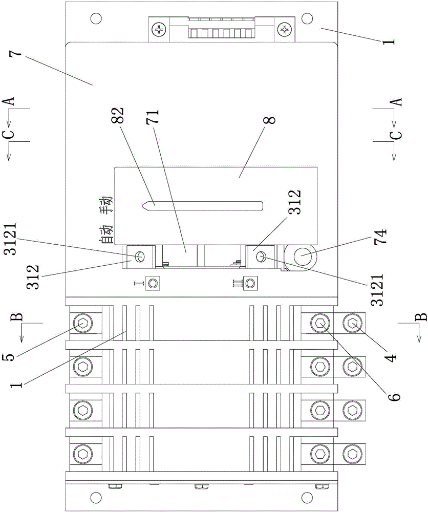
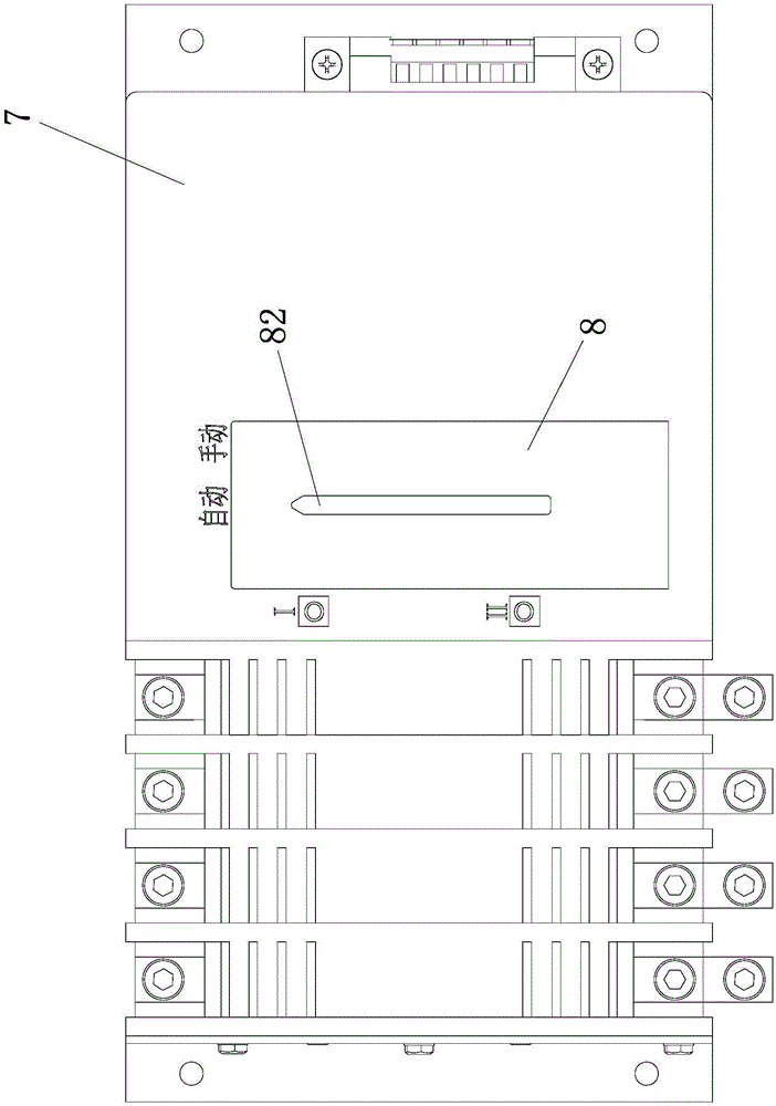
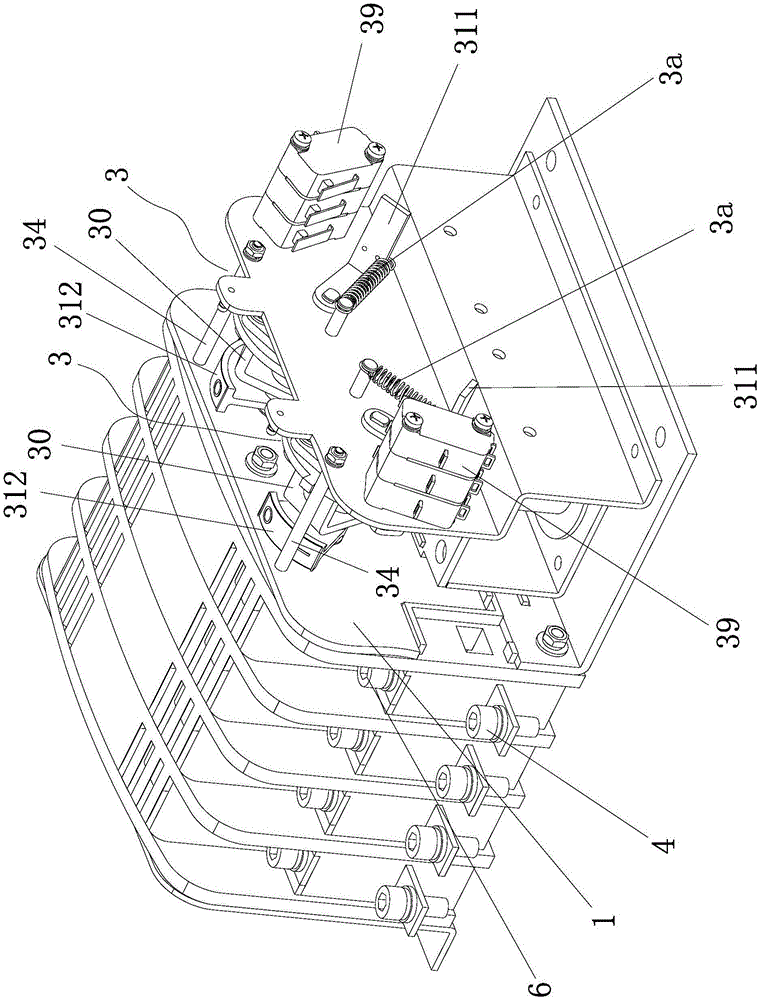
[0038] Figure 1 to Figure 13 As shown, a transfer switch includes a base 1, and two sets of contact mechanisms 2 and two sets of reversing mechanisms 3 are installed on the base 1, and each set of reversing mechanisms 3 drives a group of contact mechanisms 2 to realize opening and closing, One set of contact mechanism 2 opens and closes the load end 4 and the common power source end 5, and the other group of contact mechanisms 2 opens and closes the load end 4 and the standby power source end 6. There is an operating shaft 31 on the base 1 and an electromagnetic coil 32 fixed on the base 1. The operating shaft 31 is used to drive the contact mechanism 2 to open and close, and a reversing plate 33 is fixed in the middle of the operating shaft 31 to reverse The plate 33 is perpendicular to the operating shaft 31, the reversing plate 33 ...


PUM


Abstract

The invention discloses a change-over switch, which comprises a base, wherein the base is provided with two groups of contact mechanisms and two sets of reversing mechanisms; each set of reversing mechanism drives one group of contact mechanisms to achieve opening and closing; each set of reversing mechanism comprises an operation rotating shaft, an electromagnetic coil, a reset pressure spring, a movable iron core, a reversing plate, a limiting rod, a linkage part, a drive pin, a connecting pin and a first tension spring; each reversing plate is provided with a guide positioning hole or a guide positioning groove; two guide bevel edges and two positioning grooves are arranged in the inner side surface of each guide positioning hole or guide positioning groove; two guide bevel edges are distributed in a splayed form; one end of each drive pin is inserted into the corresponding guide positioning hole or guide positioning groove; when the electromagnetic coils are energized, the corresponding operation rotating shafts drive the corresponding contact mechanisms to open and close; when the electromagnetic coils are de-energized, the reset pressure springs drive the corresponding movable iron cores to reset; and the first tension springs drive the corresponding drive pins to be matched in the corresponding positioning grooves to position the corresponding reversing plates and operation rotating shafts. The change-over switch is compact in structure, relatively small in volume and relatively high in action reliability.

Description

technical field [0001] The invention relates to the technical field of transfer switch manufacturing. Background technique [0002] A transfer switch is a switching device that can be used for two or more power sources or load conversions. Transfer switches are widely used in various places that require uninterrupted power supply, which realizes the conversion of load lines between two power sources to ensure the reliability of power supply for users. [0003] In 2010, an invention patent with the patent number ZL200810005018.5 and the name "Continuous Dual Power Transfer Switch" was published, which includes the housing, contact opening and closing system and mechanical transmission system; its structural features are: this kind of non-interruptible The dual power transfer switch includes two mutually independent mechanical transmission systems and two mutually independent contact opening and closing systems, and each mechanical transmission system drives a contact opening...

Claims


Application Information

Patent Timeline
IPC IPC(8): H01H3/28H01H9/26
CPCH01H3/28H01H9/26
Inventor 尤安顺谢燕明吴作珍
Owner 柏法瑞电气(厦门)有限公司
Why Eureka
Try Eureka