

Pulse solid-state power amplifier and design method
A solid-state power and amplifier technology, used in power amplifiers, amplifiers, high-frequency amplifiers, etc., to reduce the pressure of power supply and heat dissipation
- Summary
- Abstract
- Description
- Claims
- Application Information
AI Technical Summary
Problems solved by technology
Method used
Image

Examples
Embodiment Construction
[0039] All features disclosed in this specification, or steps in all methods or processes disclosed, may be combined in any manner, except for mutually exclusive features and / or steps.
[0040] Any feature disclosed in this specification, unless specifically stated, can be replaced by other alternative features that are equivalent or have similar purposes. That is, unless expressly stated otherwise, each feature is one example only of a series of equivalent or similar features.
[0041] Relevant description of the present invention:
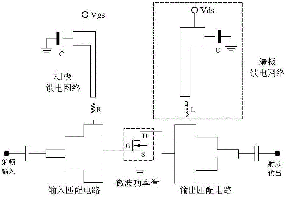
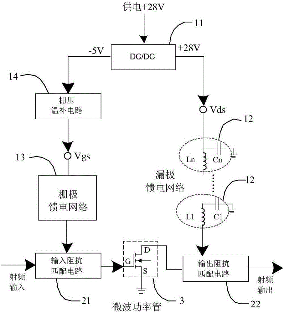
[0042] 1. The grid bias circuit is to provide the required grid voltage to the power tube to make it conduct. The drain bias circuit is to provide the DC energy required for power tube amplification. Both the amplifier input matching network and the amplifier output matching network are designs in the prior art. The gate stabilizing circuit supplies the negative voltage, and the drain feed network supplies the positive voltage.
[0043] 2. Ge...
PUM
 Abstract
Description
Claims
Application Information