
Antenna calibration method and device

An antenna calibration and to-be-calibrated technology, applied in radio transmission systems, receiver monitoring, electrical components, etc., can solve the problems of long distance between the RF antenna channel and the reference RF antenna channel, reducing the efficiency of the calibration process and calibration performance, etc. Calibrate performance, reduce hardware implementation complexity, and ensure the effect of accuracy

Active Publication Date: 2019-02-05
CHINA MOBILE COMM GRP CO LTD
View PDF6 Cites 0 Cited by
  • Summary
  • Abstract
  • Description
  • Claims
  • Application Information

AI Technical Summary

Problems solved by technology

[0033] It can be seen that in the prior art, for the reciprocity calibration method of the distributed multi-antenna system, it is necessary to select a certain radio frequency antenna channel as a fixed parameter radio frequency antenna channel. In a large-scale antenna system, the number of radio frequency antenna channels will be large , in this way, the distance between the remote RF antenna channel and the reference RF antenna channel will be very far, resulting in a difference of tens of dB in the signal-to-noise ratio of different RF antenna channels, which reduces the efficiency and calibration performance of the calibration process

Method used


Image

  • Antenna calibration method and device
  • Antenna calibration method and device
  • Antenna calibration method and device

Examples


Embodiment Construction

[0095] The following will clearly and completely describe the technical solutions in the embodiments of the present invention in conjunction with the accompanying drawings in the embodiments of the present invention. Obviously, the described embodiments are only some of the embodiments of the present invention, not all of them. Based on the embodiments of the present invention, all other embodiments obtained by persons of ordinary skill in the art without making creative efforts belong to the protection scope of the present invention.

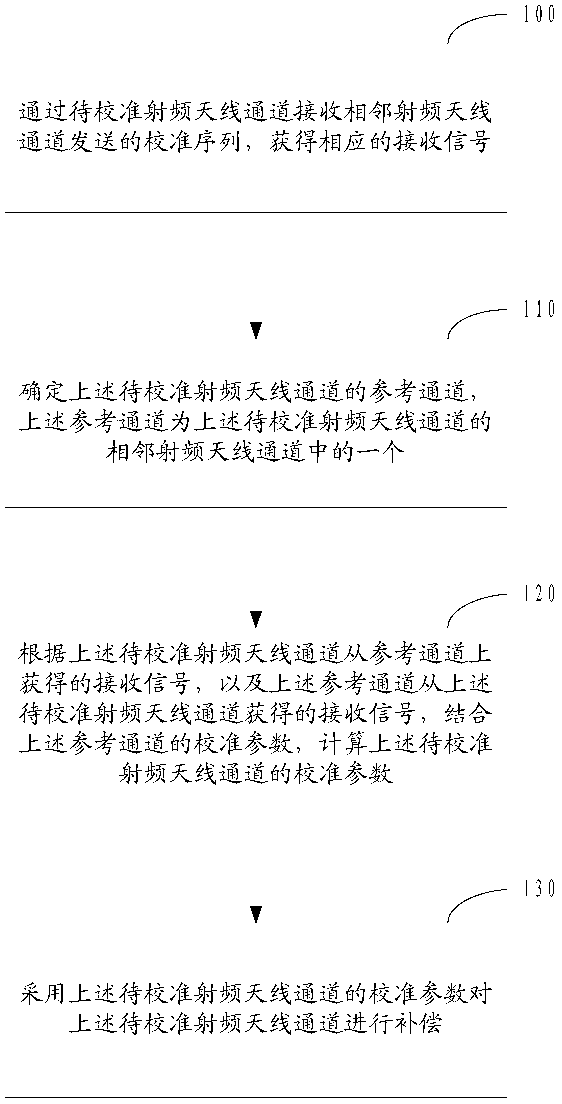
[0096] In order to improve the efficiency and calibration performance of the calibration process in LSAS, in the embodiment of the present invention, a fixed radio frequency antenna channel is no longer selected as the reference radio frequency antenna channel, but the calibration sequence is sent sequentially through each radio frequency antenna channel. The radio frequency antenna channel receives the calibration sequence sent by the correspon...


PUM


Abstract

The invention belongs to the wireless communication field and relates to an antenna calibration method and apparatus. The method is applicable to a distributed multi-antenna system without a calibration network. According to the method, a fixed radio frequency antenna channel is not selected as a reference radio frequency antenna channel any more, while, a radio frequency antenna channel to be calibrated and an adjacent radio frequency antenna channel receive calibration sequences from each other and send calibration sequences to each other; the adjacent radio frequency antenna channel is adopted as a reference channel; and the calibration parameters of the radio frequency antenna channel to be calibrated are calculated based on the calibration parameters of the reference channel. Thus, when a plurality of radio frequency antenna channels to be calibrated are calculated, the radio frequency antenna channels to be calibrated are calibrated sequentially; and calibration is not affected by the number of antennas, calibration networks and the selection of reference radio frequency antenna channels; and since adjacent radio frequency antenna channels are close to each other, a signal to noise ratio is improved, and calibration accuracy is improved compared with a calibration method according to which a fixed radio frequency antenna channel is selected.

Description

technical field [0001] The present invention relates to the field of wireless communication, in particular to an antenna calibration method and device. Background technique [0002] With the rapid increase of data traffic in wireless communication systems, the requirements for the capacity of wireless communication systems are getting higher and higher. At present, "invisible" base stations have received extensive attention. "Invisible" base stations have realized the integration of wireless base station deployment and environment. The perfect integration, and at the same time the improvement of system capacity through space division multiple access technology, is an important part of China Mobile's "green and flexible" 5G research and development concept. The "stealth" base station adopts large-scale antenna system (Large-scale Antenna System, LSAS) technology and compact active RF antenna module (SmarTile), in which SmarTile uses highly integrated, low power consumption, l...

Claims


Application Information

Patent Timeline
Patent Type & Authority Patents(China)
IPC IPC(8): H04B17/12H04B17/21H04B7/0413
Inventor 倪吉庆朱勇旭王桂珍潘振岗易芝玲
Owner CHINA MOBILE COMM GRP CO LTD
Learn More