Safety power optimization method for wireless mesh network

A power optimization and network technology, applied in the field of communication networks, can solve the problems of increased broadcast delay and increased interference range

Inactive Publication Date: 2017-03-15
高道华
View PDF4 Cites 0 Cited by
  • Summary
  • Abstract
  • Description
  • Claims
  • Application Information

AI Technical Summary

Problems solved by technology

The reason why power control is considered is because of the interference caused by it. If we assign a higher transmit power to a node, the node can broadcast at a higher rate, and its child nodes can receive packets in a shorter time and forward them to The next layer of child nodes, but at the same time, the interference range of this node will also increase, and the total broadcast delay will increase

Method used


Image

  • Safety power optimization method for wireless mesh network
  • Safety power optimization method for wireless mesh network
  • Safety power optimization method for wireless mesh network

Examples


Embodiment Construction

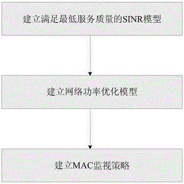
[0028] To achieve the above object, the technical scheme of the present invention is as follows:

[0029] The first step is to establish a SINR constraint model that meets the minimum service quality, specifically:

[0030]

[0031]

[0032] The second step is to establish a network power optimization model, specifically:

[0033]

[0034] min ΔP ref

[0035]

[0036]

[0037]

[0038]

[0039]

[0040]

[0041]

[0042]

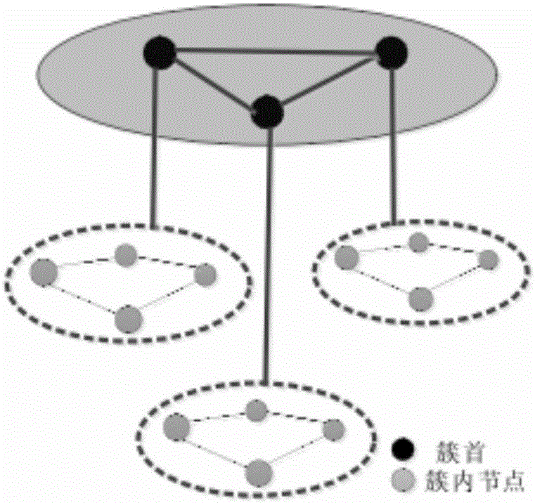
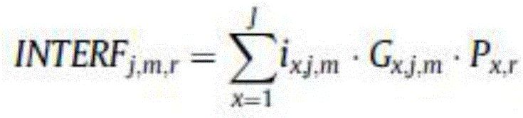
[0043] Divide the network into multiple cells, {1,2,3,...,J} is a set of cells, {1,2,3,...,M j} is the user set of the jth cell, {1,2,3,...,R} is the set of available frequency resource blocks, G j,j,m is the channel gain between the jth cell base station and the mth user in the jth cell, P j,r is the transmission power allocated to the rth frequency block in the jth cell, is the interference power generated by the rth frequency block allocated to the mth user in the jth cell, i x,j,m is a decision variable, if the wir...


PUM


Abstract

The invention aims to the problem that a network resource is difficult to realize flexible optimization management. Through establishing an SINR restraint model and a network power optimization model which meet a minimum service quality, as well as an MAC monitoring strategy, the energy resource optimization management for the wireless mesh network is realized.

Description

technical field [0001] The invention relates to the field of communication networks, in particular to power control and optimization theory. Background technique [0002] As a wireless broadband access technology based on TCP / IP, wireless Mesh network combines the advantages of WLAN and Ad Hoc, supports many-to-many network node structure, and has self-management, self-organization, multi-hop routing, It is a distributed network with high speed, large capacity and wide coverage. In a sense, WMN pays more attention to a decentralized network construction mechanism, and its structure is as follows: figure 1 shown. [0003] In recent years, power control and transmission scheduling in wireless mesh networks has been a hot topic in academic circles. In a wireless mesh network, a gateway node often needs to broadcast a data packet to all mesh routers in the backbone network, and reducing the overall broadcast delay can improve the quality of service. The minimum delay broadca...

Claims


Application Information

Patent Timeline
IPC IPC(8): H04W52/34
CPCH04W52/34
Inventor 黄东龙华杨涌
Owner 高道华
Why Eureka
Try Eureka