

A method and device for separating uranium particles
A separation method, technology of a separation device, applied to uranium particles
In the field of separation methods and devices, it can solve problems such as high requirements, large interference, and low efficiency, and achieve the effect of rapid separation and easy operation
Active Publication Date: 2012-10-17
BEIJING RES INST OF URANIUM GEOLOGY
View PDF0 Cites 2 Cited by
- Summary
- Abstract
- Description
- Claims
- Application Information
AI Technical Summary
Problems solved by technology
2003), but this method is quite difficult for the selection and separation of uranium particles, the efficiency is low, the requirements for operators are high, and the labor intensity is also low.
Although the SIMS method is fast, the interference is greater than that of the FT-TIMS method
Method used
View moreImage
Smart ImageViewing Examples

Examples
Embodiment 1
[0022]
Embodiment 2
[0029]
[0030] The uranium particle separation device used in the present invention is described in detail below.
Login to View More PUM
| Property | Measurement | Unit |
|---|---|---|
| wavelength | aaaaa | aaaaa |
Abstract
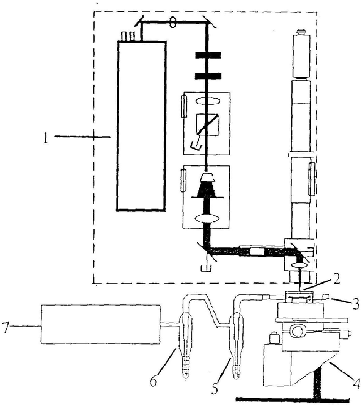
The invention relates to a method and device for separating uranium particles. The method includes adopting the fission track etching method to obtain the fission track of uranium on the fission track etching film, and then using a laser beam to focus on the fission track of uranium to evaporate the uranium particles, and carry the evaporated uranium particles Into the nitric acid absorption solution. The uranium particle separation device of the present invention includes a sample moving platform, a sample chamber is arranged above the sample moving platform, a laser for generating laser beams is located above the sample chamber, one side of the sample chamber is connected with an air filter, and the other side is connected with an absorption tube The air inlet is connected, the gas outlet of the absorption pipe is connected with the atmospheric sampler, and the nitric acid absorption liquid is filled in the absorption pipe. Through the uranium particle separation method and device of the invention, the rapid separation of uranium particles can be realized, and the operation is simple and convenient.
Description
A method and device for separating uranium particles Technical field The present invention relates to a kind of separation technique used in environmental sampling check analysis technique, be specifically related to a kind of uranium particle Separation methods and devices. Background technique Because overall analysis can only reflect the information that sample is carried to a certain extent, can not obtain the information carried by uranium particle Therefore, particle analysis has become the focus of research and application of environmental sampling verification analysis technology. Currently, the International Atomic Energy The particle analysis method adopted by the institution and its network laboratories is fission track identification-thermal surface ionization mass spectrometry (FT-TIMS) Determination of isotopic abundance ratios of uranium or plutonium particles, and determination of isotopic abundance of uranium particles by secondary ion mass spectromet...
Claims
Login to View More Application Information
Patent Timeline
 Patent Type & AuthorityPatents(China)
IPC IPC(8): G01T5/10G01N23/222G21K1/00
Inventor郭冬发李金英崔建勇谭靖武朝辉张彦辉
OwnerBEIJING RES INST OF URANIUM GEOLOGY