Continuous punching die

A mold and punching technology, which is applied in the field of continuous punching molds, can solve problems such as heavy workload, inaccurate punching positions, waste of materials, etc., and achieve the effects of improving service life, precise punching positions, and reducing costs

Inactive Publication Date: 2017-03-22
芜湖市夯福机械模具有限公司
View PDF5 Cites 5 Cited by
  • Summary
  • Abstract
  • Description
  • Claims
  • Application Information

AI Technical Summary

Problems solved by technology

[0002] In machining production, it is often necessary to open holes or grooves on metal materials. If drilling or milling is used, the workload is large, the work efficiency is low, and it is not safe.
The use of punching die processing can improve productivity, and the product quality is stable and safe, but there are some defects in the punching die in the prior art. The existing punching die has only one punching head, and only one punching head can be punched at a time. Holes, if continuous multiple holes are punched on the metal material, it is necessary to repeat the punching action again and again to complete the punching of multiple holes, and when the continuous hole is punched, the metal material is prone to deformation, punching The position of the hole is not accurate enough, resulting in a low forming rate of the hole, resulting in defective products, wasting materials, and increasing the cost

Method used


Image

  • Continuous punching die
  • Continuous punching die
  • Continuous punching die

Examples


Embodiment Construction

[0016] The content of the present invention will be described below in conjunction with specific embodiments.

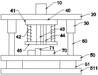
[0017] like figure 1 As shown, it is a structural schematic diagram of the continuous punching die of the present invention. The continuous punching die relates to the technical field of stamping die manufacturing and is used for stamping and forming of multiple holes on metal materials, including a die handle 10 and an upper template 20 , guide sleeve 30, punch 40, lower template 50, guide post 60, die 70, mold handle 10 is vertically arranged directly above upper template 20, guide sleeve 30 is located at both sides of upper template 20, and punch 40 is installed on Just below the upper template 20, including a fixed plate 41, a guide device 42 with a spring, a first punching head 43, a second punching head 44, and a backing plate 45, the top of the fixed plate 41 is connected to the upper template 20, and the bottom is connected to the second A punching head 43 a...


PUM


Abstract

The invention discloses a continuous punching die. The continuous punching die comprises a die handle, an upper die plate, guide sleeves, a convex die body, a lower die plate, guide pillars and a concave die body, wherein the die handle is vertically arranged over the upper die plate; the guide sleeves are arranged on two sides of the upper die plate; and the convex die body is installed under the upper die plate. The continuous punching die further comprises a fixing plate, guide devices with springs, a first punch head, a second punch head and a base plate, wherein the upper portion of the fixing plate is connected with the upper die plate, and the lower portion of the fixing plate is connected with the first punch head and the second punch head; the upper portions of the guide devices with the springs are connected with the fixing plate, and the lower portions of the guide devices with the springs are connected with the base plate; the guide pillars are arranged on two sides of the lower die plate; the upper die plate and the lower die plate are connected together through sleeving connection of the guide sleeves and the guide pillars; the concave die body is installed on the lower die plate and under the convex die body, and the concave die body comprises a limiting plate which is connected with the concave die body through a spring. The continuous punching die can punch multiple holes, achieve rapid forming, guarantee accurate positions of punched holes, and conduct continuous punching, the efficiency is high, the service life of the punch heads can be prolonged, and the cost is lowered.

Description

technical field [0001] The invention relates to the technical field of dies, in particular to a continuous punching die. Background technique [0002] In machining production, it is often necessary to open holes or grooves on metal materials. If drilling or milling is used, the workload is large, the work efficiency is low, and it is not safe. The use of punching die processing can improve productivity, and the product quality is stable and safe, but there are some defects in the punching die in the prior art. The existing punching die has only one punching head, and only one punching head can be punched at a time. Holes, if continuous multiple holes are punched on the metal material, it is necessary to repeat the punching action again and again to complete the punching of multiple holes, and when the continuous hole is punched, the metal material is prone to deformation, punching The position of the hole is not accurate enough, resulting in a low forming rate of the hole, ...

Claims


Application Information

Patent Timeline
Patent Type & Authority Applications(China)
IPC IPC(8): B21D28/34
CPCB21D28/34
Inventor 陶老夯陶庭富
Owner 芜湖市夯福机械模具有限公司
Why Eureka
Try Eureka