Anti-collision energy absorbing device for protecting hazardous chemical transporter tank bodies

A technology of energy-absorbing devices and hazardous chemicals, applied in the direction of bumpers, etc., can solve the problems of increasing the turning radius of the vehicle, lack of layout and reinforcement, and little effect. The effect of improving buffer capacity

Pending Publication Date: 2017-03-22
CCCC HUAAN TECH TIANJIN CO LTD
View PDF7 Cites 0 Cited by
  • Summary
  • Abstract
  • Description
  • Claims
  • Application Information

AI Technical Summary

Problems solved by technology

At present, the structural strength of the automotive energy-absorbing boxes on the market is not high, and there is no reasonable layout to strengthen them, and the energy-absorbing effect is not good, especially for the heavy-duty hazardous chemical transport vehicles. Damage to the storage tanks in the storage tanks can easily lead to secondary disasters, ranging from polluting the environment to causing major personal casualties. The effect of absorbing energy is very small. If you want to improve the energy-absorbing effect, you can only make a large-scale energy-absorbing device with a large volume and complex structure, which not only increases the weight of the vehicle too much, but also because the energy-absorbing device is installed on the The rear of the vehicle, so the turning radius of the vehicle is also increased, it is not easy to drive, and there are unsafe factors

Method used


Image

  • Anti-collision energy absorbing device for protecting hazardous chemical transporter tank bodies
  • Anti-collision energy absorbing device for protecting hazardous chemical transporter tank bodies
  • Anti-collision energy absorbing device for protecting hazardous chemical transporter tank bodies

Examples


Embodiment Construction

[0027] It should be noted that, in the case of no conflict, the embodiments of the present invention and the features in the embodiments can be combined with each other.

[0028] In describing the present invention, it should be understood that the terms "center", "longitudinal", "transverse", "upper", "lower", "front", "rear", "left", "right", " The orientations or positional relationships indicated by "vertical", "horizontal", "top", "bottom", "inner" and "outer" are based on the orientations or positional relationships shown in the drawings, and are only for the convenience of describing the present invention and Simplified descriptions, rather than indicating or implying that the device or element referred to must have a particular orientation, be constructed and operate in a particular orientation, and thus should not be construed as limiting the invention. In addition, the terms "first", "second", etc. are used for descriptive purposes only, and should not be understood ...


PUM


Abstract

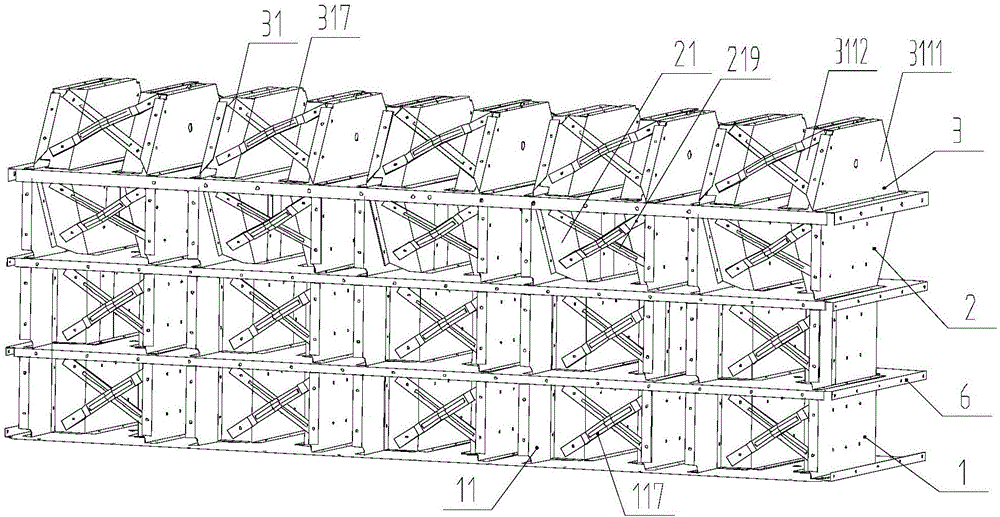
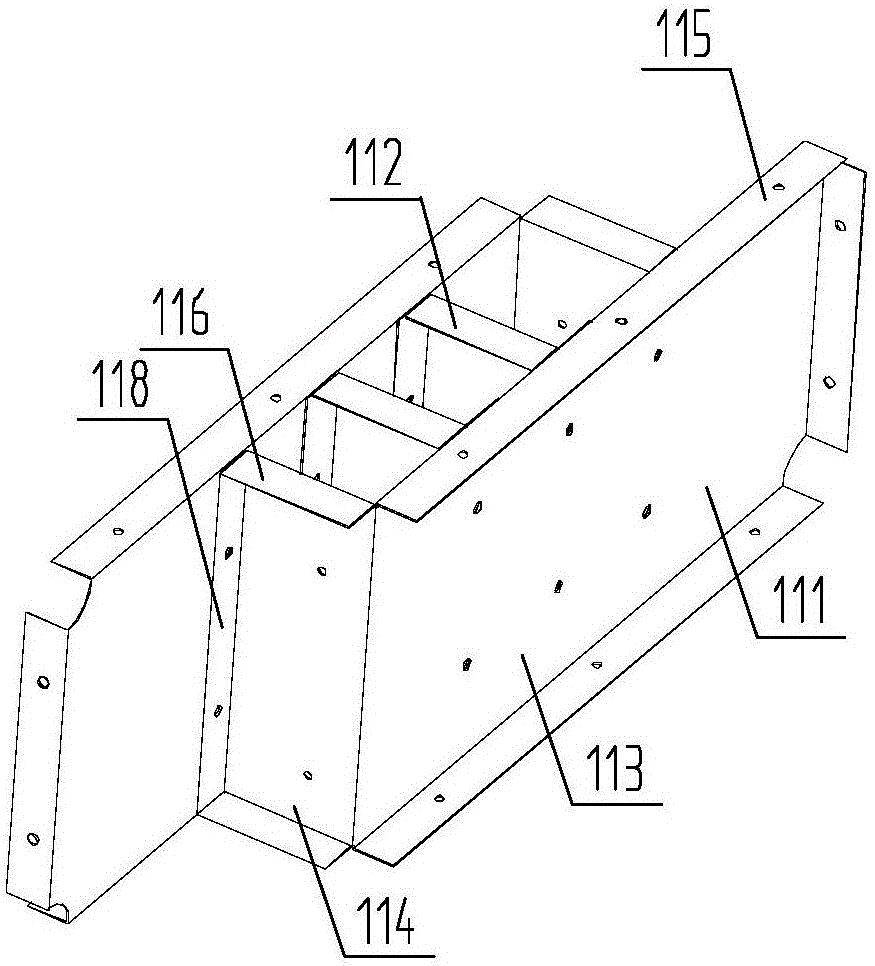
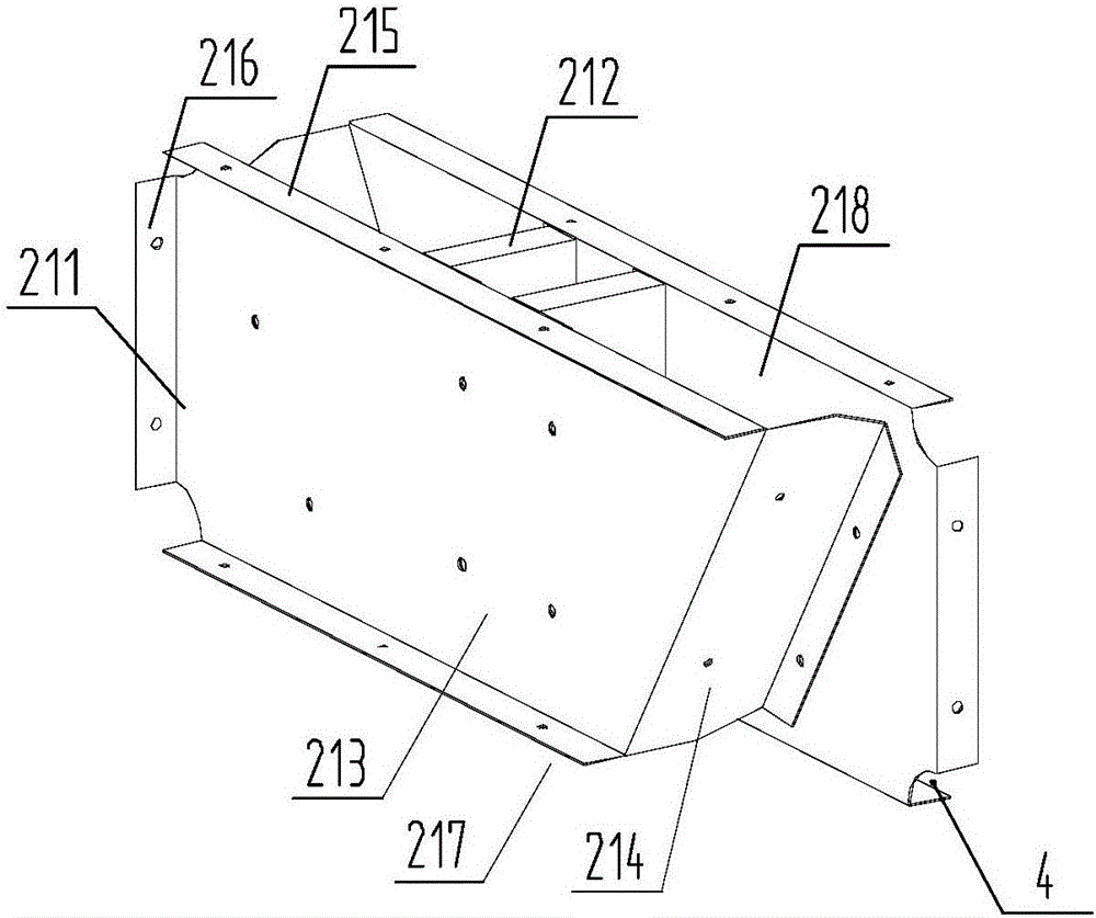
The invention provides an anti-collision energy absorbing device for protecting hazardous chemical transporter tank bodies. The anti-collision energy absorbing device comprises a lower-layer buffer supporting structure, a middle-layer buffer supporting structure, an upper-layer buffer supporting structure, and supporting partition plates, wherein each of the supporting partition plates is arranged between every two supporting structures; the lower-layer buffer supporting structure comprises a plurality of lower-layer supporting units arranged side by side; every two adjacent lower-layer supporting units are connected through a lower-layer supporting and connecting plate; the middle-layer buffer supporting structure comprises a plurality of middle-layer supporting units arranged side by side; every two adjacent middle-layer supporting units are connected through a middle-layer supporting and connecting plate; the upper-layer buffer supporting structure comprises a plurality of upper-layer supporting units arranged side by side; and every two adjacent upper-layer supporting units are connected through an upper-layer supporting and connecting plate. According to the anti-collision energy absorbing device disclosed by the invention, the structure design is reasonable, the overall structural strength of the anti-collision energy absorbing device accords with stress characteristics during a vehicle collision, and the buffer effects and energy absorbing effects are very good.

Description

technical field [0001] The invention belongs to the technical field of vehicle anti-collision equipment, and in particular relates to an anti-collision energy-absorbing device for protecting the tank body of a hazardous chemical transport vehicle. Background technique [0002] At present, the number of dangerous chemical transport vehicles in my country is about 300,000. Due to some objective reasons, rear-end collision accidents occur frequently. When a vehicle hits an obstacle ahead at a relatively high speed, the vehicle will receive a large impulse, resulting in a large obstacle acceleration that makes the vehicle drop from high speed to a standstill in an instant, and the original large kinetic energy is almost completely converted into the internal energy of the vehicle, making The vehicle was severely damaged and deformed, resulting in casualties of people in the cockpit. Therefore, in vehicle design, a crash box that absorbs these energies is usually installed at th...

Claims


Application Information

Patent Timeline
IPC IPC(8): B60R19/18B60R19/44
CPCB60R19/18B60R19/44
Inventor 高扬
Owner CCCC HUAAN TECH TIANJIN CO LTD
Why Eureka
Try Eureka