Material frame buffering cushioning device

A buffer device and material rack technology, applied in the field of material racks, can solve problems such as too late to operate, fast delivery of parts, and affect work efficiency, so as to achieve high work efficiency, low cost, and avoid over-fast delivery

Inactive Publication Date: 2017-03-22
WUXI MINGZHU TURBOCHARGER MFG
View PDF6 Cites 3 Cited by
  • Summary
  • Abstract
  • Description
  • Claims
  • Application Information

AI Technical Summary

Problems solved by technology

[0002] In the production process, the storage, operation and anti-collision of various parts are necessary means in production management. The material rack is a common equipment in production-oriented enterprises, which can be used to pl

Method used


Image

  • Material frame buffering cushioning device
  • Material frame buffering cushioning device

Examples


Embodiment Construction

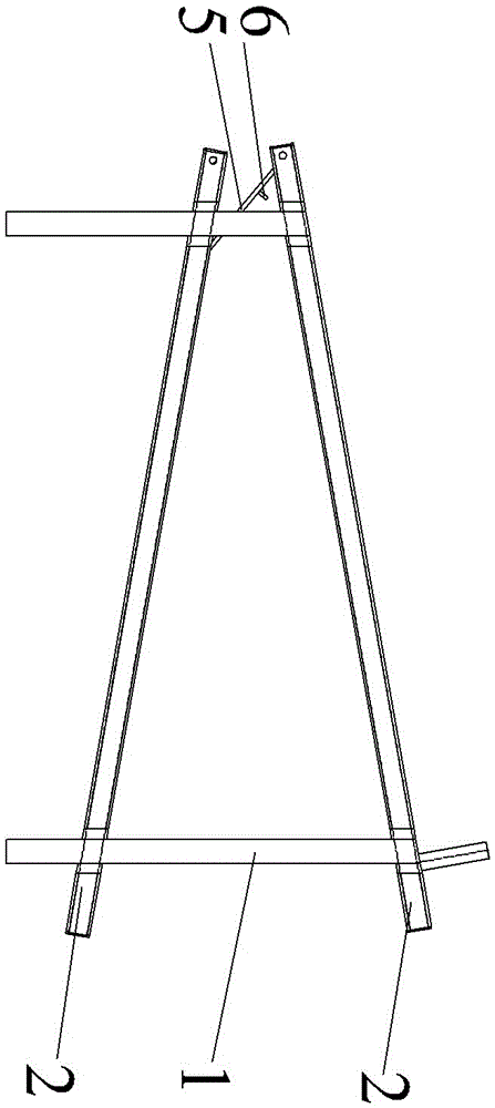
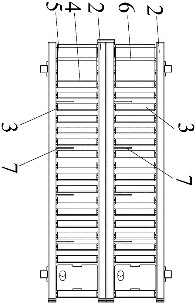
[0011] like figure 1 , figure 2 As shown, the present invention comprises frame 1, and frame 1 is provided with two layers of conveying frame 2, and conveying frame 2 is inclined arrangement, and the inclination angle of conveying frame 2 is 36 °, is convenient to automatic slide of workpiece; Frame 2 also can be provided with a plurality of side-by-side conveyings according to the situation, and is preferably 2, thereby improves work efficiency; Every layer of conveying frame 2 is all provided with conveying roller 3, after workpiece is placed on conveying frame 2, by conveying roller 3 automatically Conveying slides down, and the end-to-end connection between the conveying racks 2 is provided with a gap 4 at the tail end of the upper conveying rack 2. The bottom of one end is connected to one end of the elastic element (not shown in the figure), and the other end of the elastic element is fixed on the conveyor frame 2 corresponding to the lower layer, and a stopper 6 is pr...


PUM

PropertyMeasurementUnit
Slopeaaaaaaaaaa

Abstract

The invention provides a material frame cushioning device. According to the material frame cushioning device, parts can be stored and conveyed conveniently, the conveying speed of the parts can be effectively cushioned, thus over-quick conveying is prevented, and working efficiency is high. The material frame cushioning device comprises a rack. Two or more layers of conveying frames are arranged on the rack obliquely, each layer of the conveying frame is provided with conveying rollers, and the conveying frames are connected end to end. A gap is formed in the tail end of each upper layer of conveying frame, and the end, corresponding to the gap, of each upper layer conveying frame is hinged to one end of a conveying plate. An elastic component is arranged at the bottom of the other end of each conveying plate, and the other end of the elastic component is fixed to the corresponding lower layer of conveying frame. Spring pieces are arranged on the conveying frames with conveying rollers arranged at intervals.

Description


Claims


Application Information

Patent Timeline
Owner WUXI MINGZHU TURBOCHARGER MFG
Why Eureka
Try Eureka