Protective device used for pulling large workpieces to move in machining workshop

A technology for large workpieces and protective devices, which is applied in the directions of transportation and packaging, delivery of filamentous materials, and thin material handling, etc. The effect of collision damage

Inactive Publication Date: 2017-03-22
重庆淬智机械有限公司
View PDF0 Cites 0 Cited by
  • Summary
  • Abstract
  • Description
  • Claims
  • Application Information

AI Technical Summary

Problems solved by technology

The steel rope is the connecting piece that realizes the mutual connection between the traction equipment and the workpiece. However, when the traction line is wound up, an adjusting roller drives the winding roller of the hoist to rotate, and the traction line is pulled from the exit of the hoist to the winding machine of the hoist. On the winding roller, because the winding roller body of the winch machine rotates continuously with the adjusting roller, the traction line entering the inner wall of the winding roller of the hoisting machine is easy to accumulate on one side of the winding roller of the hoisting machine, causing the winding roller of the hoisting machine to The other side is free, that is, the traction lines accumulated on the take-up roller of the winch are polarized, and the distribution is extremely scattered
At the same time, the tension of the traction wire drawn into the winding roller of the hoist cannot be guaranteed, so that the inner diameters of the traction coils on the same traction wire layer formed into turns are different, and mutual extrusion is easily formed between two adjacent traction wire layers, seriously It is easy to cause the traction line to be stuck on the winding roller of the hoist when it appears again, which increases the difficulty of moving large workpieces

Method used


Image

  • Protective device used for pulling large workpieces to move in machining workshop

Examples


Embodiment 1

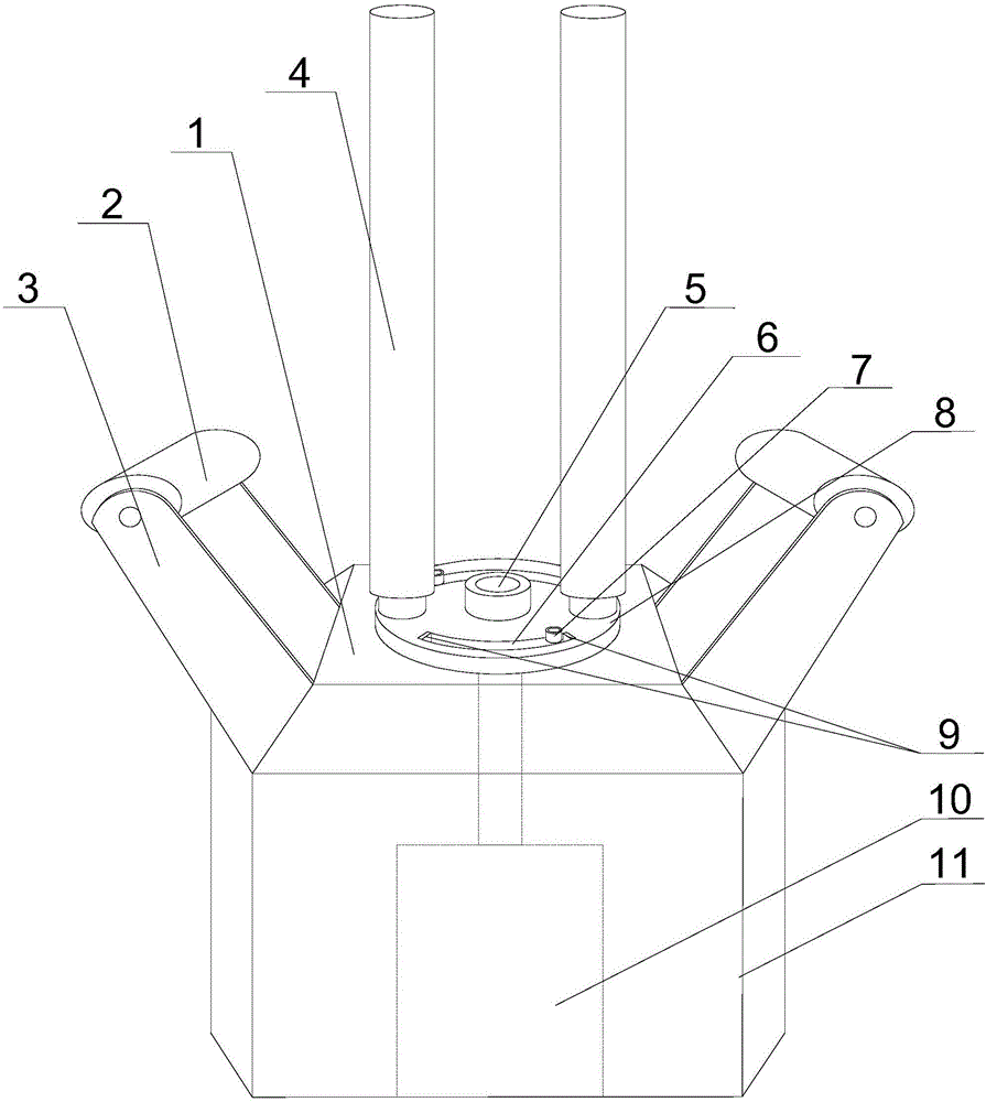
[0021] Such as figure 1 As shown, this embodiment includes a workbench and a mount 1 fixed on the workbench, brackets 3 are respectively fixed on both sides of the mount 1, and a roller 2 whose axis is perpendicular to the moving direction of the traction line is rotatably arranged on the On the bracket 3, a turntable 8 is arranged in the middle of the mounting seat 1 through the rotation of the central shaft 5, and two vertical adjustment rollers 4 are symmetrically arranged on the turntable 8 along its center of circle. An arc-shaped limiting groove 6, and two fixing holes are arranged symmetrically along its axis on the mounting base 1, and the end of the positioning rod 7 moves vertically through the limiting groove 6 and is connected with the fixing holes. At least two annular grooves are arranged on the regulating roller 4, and the regulating roller 4 is sleeved on the regulating roller 4, and a travel switch 9 which is rotatably arranged on the circular groove is includ...


PUM

PropertyMeasurementUnit
Central angleaaaaaaaaaa

Abstract

The invention discloses a protective device used for pulling large workpieces to move in a machining workshop. The protective device comprises a workbench and a mounting base, wherein brackets are fixedly arranged at the two sides of the mounting base separately; rollers are rotatably arranged on the brackets; a rotary disc is rotatably arranged on the mounting base; two regulating rollers are arranged on the rotary disc; two limiting slots are formed in the rotary disc; two fixing holes are formed in the mounting base; end part of a positioning rod perpendicularly and movably penetrates through the limiting slots, and then is connected with the fixing holes; a step motor is arranged in the workbench; a central shaft is connected with an output end of the step motor; travel switches are arranged at the two ends of each limiting slot; and the travel switches are connected with the step motor through controllers. When the positioning rod is in contact with the travel switches, the travel switches send a signal to the controller, the controller sends a control command to the step motor, and the step motor starts to rotate reversely, so that a traction rope is forced to change course again; and on the premise of preventing the positioning rod from being in hard contact with the rotary disc, the traction rope is guaranteed to uniformly roll on a rolling roller.

Description

technical field [0001] The invention relates to the field of machine shop processing, in particular to a protection device for pulling and moving a large workpiece in a machine shop. Background technique [0002] In the machining workshop, ordinary manual labor cannot move large workpieces normally, and traction equipment similar to hoists is usually needed to realize the transfer of workpieces. The steel rope is the connecting piece that realizes the mutual connection between the traction equipment and the workpiece. However, when the traction line is wound up, an adjusting roller drives the winding roller of the hoist to rotate, and the traction line is pulled from the exit of the hoist to the winding machine of the hoist. On the winding roller, because the winding roller body of the winch machine rotates continuously with the adjusting roller, the traction line entering the inner wall of the winding roller of the hoisting machine is easy to accumulate on one side of the w...

Claims


Application Information

Patent Timeline
IPC IPC(8): B65H54/28
CPCB65H54/286B65H2701/35
Inventor 陈和平
Owner 重庆淬智机械有限公司
Why Eureka
Try Eureka