A portable cleaning device for porous tube sheets

A technology for cleaning equipment and porous tube sheets, which is applied to the cleaning of rotating equipment, lighting and heating equipment, and flushing. It can solve the problems of long cleaning time, difficult cleaning of tube sheets, and difficult cleaning of tube holes, and achieve the effect of avoiding clogging

Active Publication Date: 2019-01-29
CHENGDU ZHIRONG ZHICHUANG INTPROP MANAGEMENT CO LTD
View PDF4 Cites 0 Cited by
  • Summary
  • Abstract
  • Description
  • Claims
  • Application Information

AI Technical Summary

Problems solved by technology

[0004] The purpose of the present invention is to provide a convenient cleaning device for porous tube sheets, which solves the problem that the existing tube sheets are very difficult to clean because there are many tube holes distributed on the surface, the cleaning time is very long and the tube holes are not easy to clean. The problem

Method used


Image

  • A portable cleaning device for porous tube sheets

Examples


Embodiment 1

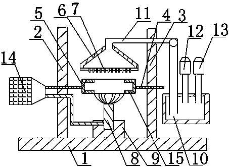
[0021] Such as figure 1 As shown, a portable cleaning device for a porous tube sheet of the present invention includes a base 1, a fixed plate A2 and a fixed plate B3 are fixed above the base 1, and a rotating shaft 4 is connected between the fixed plate A2 and the fixed plate B3, and the rotating shaft 4 A hollow shelf 5 with a fixed tube sheet is installed on it, and a conical nozzle 6 is installed above the shelf 5. A plurality of nozzles 7 are arranged at the lower end of the nozzle 6. The nozzle 6 is connected with a water storage device. A rotating brush 8 is installed, and the lower end of the rotating brush 8 is connected with a telescopic rod 9, and the telescopic rod 9 is fixed on the base 1. Both the rotating shaft 4 and the rotating brush 8 are connected to the motor 14, and the motor 14 is located on the side of the fixed plate A2 away from the fixed plate B3. The water storage device includes a reservoir 10 connected to the nozzle 6, the reservoir 10 is located ...

Embodiment 2

[0024] Based on Embodiment 1, a cold water bottle 12 and a thermos bottle 13 are connected above the reservoir 10, and the thermos bottle 13 is covered with an insulation layer. The water for cleaning the tube sheet can be selected according to the season and the appropriate water temperature, and can also be selected according to the stains on the tube sheet, and a detergent for cleaning oil stains or a special cleaning agent for the tube sheet can also be added to the reservoir.

Embodiment 3

[0026] Based on the above embodiment, the rack 5 is provided with a plurality of baffles 15 for fixing the tube sheet, and the baffles 15 above the rack 5 are connected to the rack 5 through hinges. Baffles are set around the frame of the storage rack to fix the tube sheet. Since the middle of the tube sheet is hollow, a baffle is required to block the tube sheet when the tube sheet is fixed on the storage rack; the baffle located above the storage rack and the storage rack The movable link is to facilitate the prevention of the tube sheet. When the tube sheet needs to be placed, just open the baffle above the shelf; the surface where the baffle contacts the tube sheet should also be provided with a rubber layer for anti-slip and anti-wear.


PUM


Abstract

The invention discloses portable cleaning equipment for a porous tube plate. The portable cleaning equipment for the porous tube plate comprises a base; a fixed plate A and a fixed plate B; a rotating shaft is connected between the fixed plate A and the fixed plate B; a hollow storage rack for fixing a tube plate is mounted on the rotating shaft; a conical spraying head is mounted above the storage rack; a plurality of spraying nozzles are arranged at the lower end of the spraying head; the spraying head is connected with a water storage device; a rotating brush is mounted below the storage rack; the lower end of the rotating brush is connected with a telescopic rod; the telescopic rod is fixed to the base. According to the portable cleaning equipment for the porous tube plate, the tube plate can be cleaned thoroughly and comprehensively at 360 degrees, the time spent in cleaning the tube plate is short, and the labour is saved.

Description

technical field [0001] The invention relates to a tube plate cleaning device, in particular to a portable cleaning device for a porous tube plate. Background technique [0002] The boiler is a kind of energy conversion equipment. The energy input to the boiler includes chemical energy and electric energy in the fuel, and the boiler outputs steam, high-temperature water or organic heat carrier with a certain amount of heat energy. The original meaning of the pot refers to the water container heated on the fire, and the furnace refers to the place where fuel is burned. The boiler includes two parts: the pot and the furnace. The hot water or steam generated in the boiler can directly provide the required heat energy for industrial production and people's life, and can also be converted into mechanical energy through a steam power device, or converted into electrical energy through a generator. Boilers that provide hot water are called hot water boilers, which are mainly used i...

Claims


Application Information

Patent Timeline
Patent Type & Authority Patents(China)
IPC IPC(8): F28G13/00F28G9/00F28G3/04
CPCF28G3/04F28G9/00F28G13/00
Inventor 黄可唯黄建伟苏伟邓艳梁俊萍
Owner CHENGDU ZHIRONG ZHICHUANG INTPROP MANAGEMENT CO LTD
Why Eureka
Try Eureka