Fiber bragg grating strain device

A fiber grating and strain sensor technology, applied in the field of optical fibers, can solve the problems of complex structure of multiple grating systems, and achieve the effect of eliminating temperature cross-interference

Active Publication Date: 2017-03-22
BEIJING UNIV OF POSTS & TELECOMM
View PDF7 Cites 1 Cited by
  • Summary
  • Abstract
  • Description
  • Claims
  • Application Information

AI Technical Summary

Problems solved by technology

Most of these methods use multiple grat

Method used


Image

  • Fiber bragg grating strain device
  • Fiber bragg grating strain device
  • Fiber bragg grating strain device

Examples


Embodiment Construction

[0016] The specific implementation manners of the present invention will be further described in detail below in conjunction with the accompanying drawings and embodiments. The following examples are used to illustrate the present invention, but are not intended to limit the scope of the present invention.

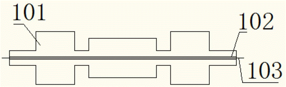
[0017] figure 1 A schematic structural diagram of a fiber grating strain sensor in the prior art is shown. As shown in the figure, the device only includes a substrate 101, and the substrate 101 is provided with a V-shaped groove 102 for placing a fiber grating 103 along the strain direction. Since the fiber Bragg grating 103 is in direct contact with the substrate, there is a strain and temperature cross-sensitivity problem in the actual sensing measurement, and the change of strain and temperature will change its Bragg wavelength, which leads to the introduction of temperature disturbance.

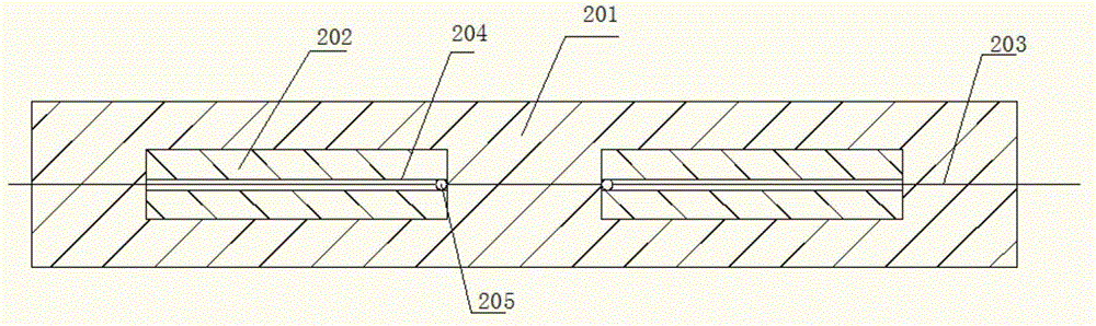
[0018] figure 2 It shows a top view of a fiber grating strain sensor disclo...


PUM


Abstract

The invention provides a fiber bragg grating strain sensor. The sensor comprises a substrate, two compensation arms and fiber bragg gratings, wherein the two compensation arms are symmetrically arranged on two sides of the substrate; one side of an upper end of each compensation arm, which is close to a substrate center, is provided with an optical fiber fixing point; one side of a lower end of the each compensation arm, which is far away from the optical fiber fixing point, is fixed to the substrate; and the fiber bragg gratings are arranged on the two compensation arms through the optical fiber fixing points. In the invention, an expansion direction of the compensation arms is opposite to an expansion direction of the substrate so that expansion quantities and the expansion directions of the substrate and the compensation arms are different, expansion quantities of the fiber bragg gratings are compensated and a temperature cross interference is eliminated.

Description

technical field [0001] The invention relates to the field of optical fiber technology, and more specifically, relates to a fiber grating strainer for eliminating temperature influence. Background technique [0002] Fiber Bragg grating is a very practical optical sensor, which has the advantages of small size and anti-electromagnetic interference. Because fiber gratings have the advantages of small size, low splicing loss, full compatibility with optical fibers, and can be embedded in smart materials, and their resonant wavelength is sensitive to changes in external environments such as temperature, strain, refractive index, and concentration, they have been used in bridges, tunnels, etc. , buildings and other large and complex structural deformation monitoring and petrochemical, power supply facility temperature monitoring and other aspects have been more and more widely used. [0003] At present, in the actual sensing and measurement of fiber Bragg gratings, there is a pro...

Claims


Application Information

Patent Timeline
IPC IPC(8): G01B11/16
Inventor 于长江张治国
Owner BEIJING UNIV OF POSTS & TELECOMM
Why Eureka
Try Eureka