Method for processing fault traveling wave of flexible DC transmission line

A transmission line, flexible direct current technology, which is applied in the direction of fault location, fault detection according to the type of conductor, measurement of electricity, etc., can solve the problem of damaged converter station, relay protection can not meet the requirements of rapidity of flexible direct current transmission line protection, fault behavior It is difficult to highlight the overall characteristics of the wave concisely and effectively, and achieve the effect of eliminating the influence of DC and low-frequency signals

Active Publication Date: 2017-03-22
TSINGHUA UNIV +1
View PDF7 Cites 9 Cited by
  • Summary
  • Abstract
  • Description
  • Claims
  • Application Information

AI Technical Summary

Problems solved by technology

However, when a short-circuit fault occurs on the flexible DC transmission line, the excessive short-circuit current will permanently damage the power electronic devices of the converter station. Therefore, it is necessary to correctly identify the fault in a very short time after the fault occurs and open the DC circuit breaker to protect the converter. Station Power Electronics
The relay protection of traditional DC transmission lines cannot meet the requirements of flexible DC transmission lines for fast protection. The protection technology and fault technology based on traveling wave principle is an ideal choice to solve this problem.
[0003] However, the current analysis method of fault traveling wave takes a single fault traveling wave head as the research object, and lacks an in-depth analysis of the characteristics of the entire wave process; and only through a single fault traveling wave head, it is difficult to highlight the overall characteristics of the fault traveling wave concisely and effectively , it is difficult to distinguish between fault traveling waves and high-frequency transient disturbances

Method used


Image

  • Method for processing fault traveling wave of flexible DC transmission line
  • Method for processing fault traveling wave of flexible DC transmission line
  • Method for processing fault traveling wave of flexible DC transmission line

Examples


Embodiment Construction

[0063] In order to understand the above-mentioned purpose, features and advantages of the present invention more clearly, the present invention will be further described in detail below in conjunction with the accompanying drawings and specific embodiments. It should be noted that, in the case of no conflict, the embodiments of the present application and the features in the embodiments can be combined with each other.

[0064] In the following description, many specific details are set forth in order to fully understand the present invention. However, the present invention can also be implemented in other ways different from those described here. Therefore, the protection scope of the present invention is not limited by the specific details disclosed below. EXAMPLE LIMITATIONS.

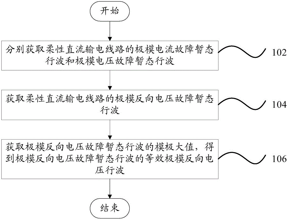
[0065] Such as figure 1 As shown, according to an embodiment of the present invention, a method for processing fault traveling waves of flexible direct current transmission lines is provided, includ...


PUM


Abstract

The invention provides a method for processing the fault traveling wave of a flexible DC transmission line. The method comprises a step of obtaining the pole mode current and pole mode voltage fault transient traveling wave of the flexible DC transmission line, a step of obtaining a pole mode reverse voltage fault transient traveling wave, a step of obtaining the modulus maximum of the pole mode reverse voltage fault transient traveling wave, and obtaining the equivalent pole mode inverse voltage travelling wave of the pole mode reverse voltage fault transient traveling wave. According to the technical scheme of the invention, the difference between the fault traveling wave and high-frequency transient interference can be effectively displayed, thus the overall characteristic of a flexible DC transmission line fault is more simple and intuitive, the influences of direct current and low frequency signal in the pole mode reverse voltage fault transient traveling wave can be eliminated, the high frequency characteristic of a traveling wave process is highlighted, the analysis difficulty of a flexible DC system downgoing wave process is reduced, and the ultra high speed flexible DC transmission line protection is possible.

Description

technical field [0001] The invention relates to the technical field of relay protection and fault detection of power systems, in particular to a method for processing fault traveling waves of flexible direct current transmission lines. Background technique [0002] Compared with traditional DC transmission technology, flexible DC transmission technology has the advantages of low harmonic level, no commutation failure problem, no reactive power compensation problem, power supply for passive systems, and independent adjustment of active power and reactive power at the same time. It has broad application prospects in our country. However, when a short-circuit fault occurs on the flexible DC transmission line, the excessive short-circuit current will permanently damage the power electronic devices of the converter station. Therefore, it is necessary to correctly identify the fault in a very short time after the fault occurs and open the DC circuit breaker to protect the converte...

Claims


Application Information

Patent Timeline
Patent Type & Authority Applications(China)
IPC IPC(8): G01R31/08
CPCG01R31/085G01R31/088
Inventor 董新洲汤兰西施慎行王宾庞辉孔明贺之渊杨杰裴翔羽
Owner TSINGHUA UNIV
Why Eureka
Try Eureka