
An electronic tag circuit

A technology of electronic tags and circuits, which is applied in the direction of instruments, calculations, and record carriers used by machines, can solve problems such as complex structures of rectification circuits and current limiting circuits, and achieve stable and reasonable output voltages, small temperature deviations, and simple circuit structures and stable effect

Active Publication Date: 2019-02-15
BEIJING SMARTCHIP SEMICON TECH CO LTD +2
View PDF9 Cites 0 Cited by
  • Summary
  • Abstract
  • Description
  • Claims
  • Application Information

AI Technical Summary

Problems solved by technology

[0010] The purpose of the present invention is to provide an electronic label circuit, so as to overcome the defects of complex structure of the existing electronic label rectification circuit and current limiting circuit

Method used


Image

  • An electronic tag circuit
  • An electronic tag circuit
  • An electronic tag circuit

Examples


Embodiment Construction

[0048] The specific embodiments of the present invention will be described in detail below in conjunction with the accompanying drawings, but it should be understood that the protection scope of the present invention is not limited by the specific embodiments.

[0049] In order to make the purpose, technical solutions and advantages of the embodiments of the present invention clearer, the technical solutions in the embodiments of the present invention will be clearly and completely described below in conjunction with the drawings in the embodiments of the present invention. Obviously, the described embodiments It is a part of embodiments of the present invention, but not all embodiments. Based on the embodiments of the present invention, all other embodiments obtained by persons of ordinary skill in the art without creative efforts fall within the protection scope of the present invention. Unless expressly stated otherwise, throughout the specification and claims, the term "co...


PUM


Abstract

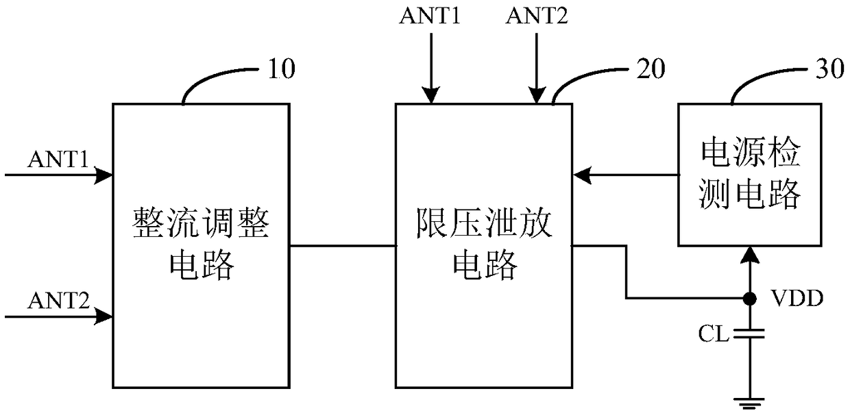
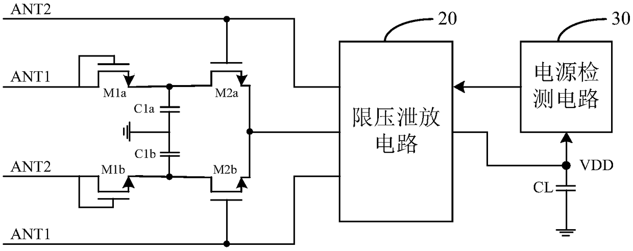
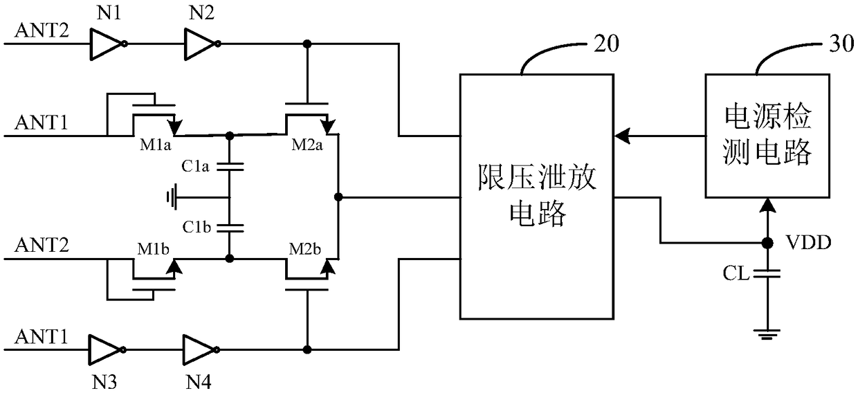
The present invention discloses an electronic tag circuit, which comprises a rectifying and regulating circuit, a voltage-limiting bleeder circuit, a power detection circuit and a voltage-stabilizing capacitor. The first input terminal of the rectifying and regulating circuit is used for receiving a first antenna signal. The second input terminal of the rectifying and regulating circuit is used for receiving a second antenna signal. The output terminal of the rectifying and regulating circuit is connected with the input terminal of the voltage-limiting bleeder circuit. The first control terminal of the voltage-limiting bleeder circuit is used for receiving the first antenna signal. The second control terminal of the voltage-limiting bleeder circuit is used for receiving the second antenna signal. The output terminal of the voltage-limiting bleeder circuit is connected with the first terminal of the voltage-stabilizing capacitor. The second terminal of the voltage-stabilizing capacitor is grounded. The input terminal of the power detection circuit is connected with the first terminal of the voltage-stabilizing capacitor. The output terminal of the power detection circuit is connected with the feedback terminal of the voltage-limiting bleeder circuit. The voltage-limiting bleeder circuit is used for conducting the voltage reduction treatment on the output voltage according to the feedback signal, the first antenna signal and the second antenna signal. The electronic tag circuit is simple and stable in structure, and eliminates the circuit emulation.

Description

technical field [0001] The invention relates to the technical field of electronic tags, in particular to an electronic tag circuit. Background technique [0002] Electronic tags are also called radio frequency tags, transponders, and data carriers; electronic tags are commonly known as RFID (Radio Frequency Identification, radio frequency identification). The electronic tag mainly includes a chip and an antenna. The chip receives microwave signals through the antenna, and sends the electronic code stored in the chip through the antenna by virtue of the energy obtained by the induced current. Among them, the voltage limiting circuit and the rectifying circuit are indispensable parts in the electronic label. The voltage limiting circuit protects the components in the chip from being damaged by the high voltage coupled by the antenna by limiting the voltage at the antenna terminal under a large field strength. The traditional voltage limiting circuit generally includes a field...

Claims


Application Information

Patent Timeline
Patent Type & Authority Patents(China)
IPC IPC(8): G06K19/07
CPCG06K19/0701G06K19/0715
Inventor 符令何洋杜蜀薇胡毅王小曼赵东艳王于波
Owner BEIJING SMARTCHIP SEMICON TECH CO LTD
Learn More