Post insulator

A technology of insulators and pillars, applied in the field of insulators, can solve problems such as fracture and inability to meet the tension requirements of insulators, and achieve the effect of reducing the failure rate

Active Publication Date: 2017-03-22
NINGBO POWER SUPPLY COMPANY STATE GRID ZHEJIANG ELECTRIC POWER +1
View PDF3 Cites 4 Cited by
  • Summary
  • Abstract
  • Description
  • Claims
  • Application Information

AI Technical Summary

Problems solved by technology

[0004] In addition, the aluminum tie wires that are fixedly connected between the overhead conductors and the post insulators often break due to friction, unev

Method used


Image

  • Post insulator
  • Post insulator
  • Post insulator

Examples


Embodiment Construction

[0028] In order to make the above objects, features and advantages of the present invention more comprehensible, specific implementations of the present invention will be described in detail below in conjunction with the accompanying drawings.

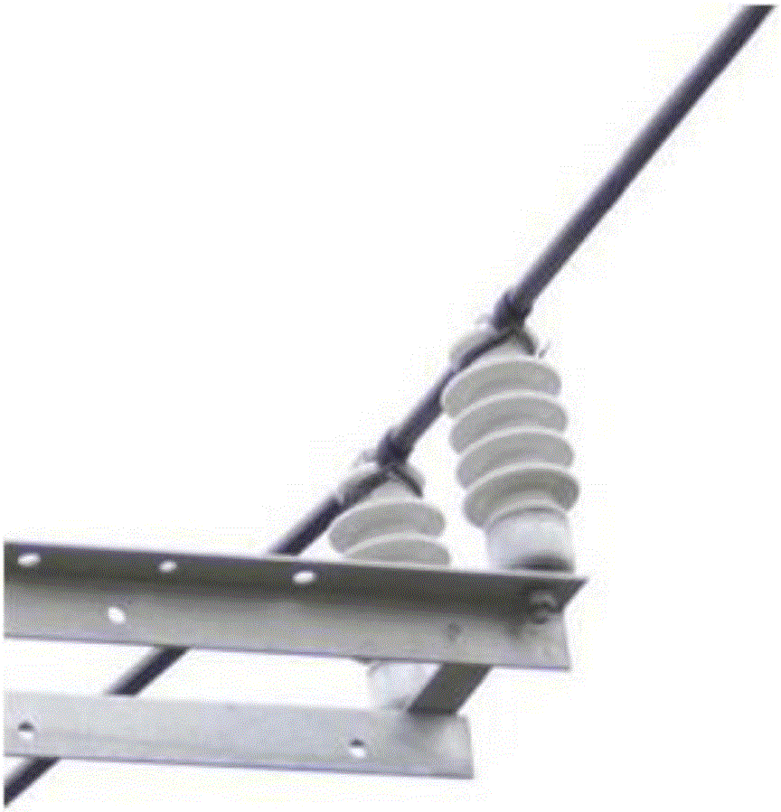
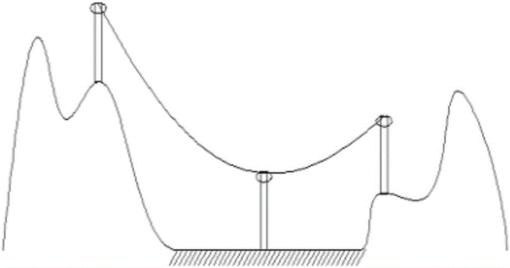
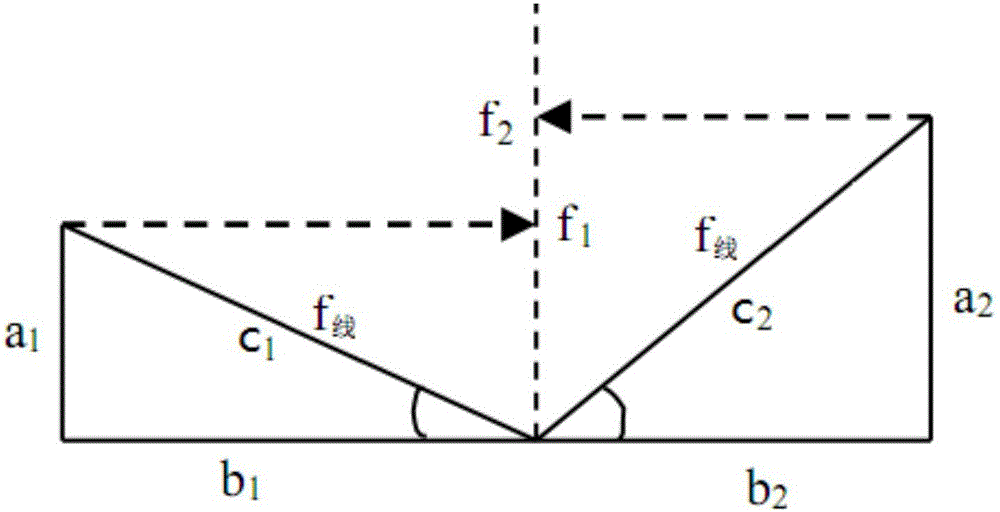
[0029] The invention provides a post type insulator to meet the tension requirement of overhead wires on the insulator in hilly terrain.

[0030] Specifically, for the post insulator, see Figure 4 to Figure 6 , including: an insulator 100, a first connector 201, a second connector 202 and a movable clamp 300; wherein:

[0031] The first connecting piece 201 is used to connect the insulator 100 and the cross arm on the pole;

[0032] The second connecting piece 202 is used to connect the insulator 100 and the movable clamp 300;

[0033] The movable wire clamp 300 is used for fixing overhead wires;

[0034] The destructive force of the insulator 100 is greater than a preset value.

[0035] Preferably, the destructive force of the in...


PUM


Abstract

The invention provides a post insulator. An insulating body and a cross arm on a pole are connected through a first connector; the insulating body and a movable clamp are connected through a second connector; an overhead conductor is fixed by the movable clamp, so that the condition of regular fractures due the adoption of an aluminum binding wire in the prior art is avoided; and the destructive force of the insulating body is greater than a preset constant value and the preset constant value is selected according to a specific application environment, so that the tension requirement of the overhead conductor in a hill terrain on the insulator can be met and the failure rate of the post insulator is reduced.

Description

technical field [0001] The invention relates to the technical field of insulators, in particular to a column insulator. Background technique [0002] The post insulator is an insulator used to fix the overhead wires in the line and keep the overhead wires insulated from the cross arm and pole. General post insulators see figure 1 , connected with the overhead wire through the aluminum tie wire, which plays a supporting role for the overhead wire. However, in the environment of hilly terrain, it often occurs figure 2 In the situation shown, due to the influence of the height difference between the poles, the post insulator on the middle pole bears a large upward pulling force of the overhead wire. [0003] see image 3 , since the pulling force of the same overhead wire at the left and right ends of the pole is equal, it is assumed that the overhead wire is figure 2 The tensile force borne by the middle electric pole is its calculated breaking force f 线 =60.329KN, aft...

Claims


Application Information

Patent Timeline
IPC IPC(8): H01B17/16
CPCH01B17/16
Inventor 钱程阮浩洁夏时哲何晓伟卫广宇
Owner NINGBO POWER SUPPLY COMPANY STATE GRID ZHEJIANG ELECTRIC POWER
Why Eureka
Try Eureka