Vacuum arc extinguish chamber with composite shielding structures

A vacuum interrupter and composite shielding technology, applied in high-voltage air circuit breakers, electrical components, electrical switches, etc., can solve problems that are not conducive to the maintenance-free performance of metal-enclosed switchgear, lengthen the production cycle of vacuum interrupters, and increase vacuum interrupters. Arc chamber production cost and other issues, to achieve the effect of improving environmental protection and economic performance, conducive to heat dissipation, and shortening the design length

Active Publication Date: 2017-03-22
XIAN HIGH VOLTAGE APP RES INST CO LTD
View PDF3 Cites 3 Cited by
  • Summary
  • Abstract
  • Description
  • Claims
  • Application Information

AI Technical Summary

Problems solved by technology

Although this structure enhances the external insulation characteristics of the vacuum interrupter, it is based on a higher solid sealing technology, which not only lengthens the production cycle of the vacuum interrupter, but also increases the production cost of the vacuum interrupter.
In addition, there is still a hidden danger of cracking in the epoxy resin sealed in the vacuum interrupter, which will not be conducive to the realization of the maintenance-free performance of the metal-enclosed switchgear; at the same time, if the vacuum interrupter is completely sealed in the epoxy resin, It will not be conducive to the heat dissipation of the vacuum interrupter

Method used


Image

  • Vacuum arc extinguish chamber with composite shielding structures
  • Vacuum arc extinguish chamber with composite shielding structures

Examples


Embodiment Construction

[0017] The present invention will be further described in detail below in conjunction with specific embodiments, which are explanations of the present invention rather than limitations.

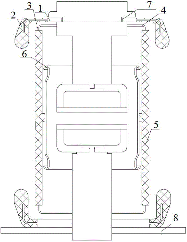
[0018] The present invention is a vacuum interrupter with composite shielding structure, such as figure 1 As shown, it includes a vacuum interrupter and a composite shielding structure arranged and implemented on the periphery of the upper and lower ends of the vacuum interrupter; the front end of the metal shield 1 in the composite shielding structure, that is, the outer edge end must exceed the metal seal The face 3 has a certain size; in this preferred embodiment at least exceeds 1 mm.

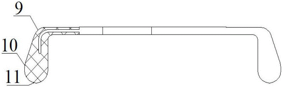
[0019] Among them, the composite shielding structure includes a metal shielding case 1 and an epoxy resin dielectric 2, which is formed by integral casting of the metal shielding case 1 and the epoxy resin dielectric 2; the front end of the metal shielding case 1 is coated with a certain thickness of the e...


PUM


Abstract

The invention discloses a vacuum arc extinguish chamber with composite shielding structures. The vacuum arc extinguish chamber is high in external insulation characteristic, capable of facilitating heat dissipation, low in epoxy resin dosage, economical and environment-friendly. The vacuum arc extinguish chamber comprises a vacuum arc extinguish chamber body and the composite shielding structures, wherein the vacuum arc extinguish chamber body comprises a ceramic shell with openings in the upper and lower ends, cover plates which are arranged at the upper and lower ends of the ceramic shell through metal sealing-connecting surfaces respectively, a static contact which passes through the cover plate at one end and is fixedly arranged in a sealing manner, and a movable contact which passes through the cover plate at the other end and is glidingly arranged in a sealing manner; each composite shielding structure comprises a metal shielding cover and an epoxy resin dielectric which are formed by pouring in a whole body; the metal shielding cover is arranged in a disc-shaped manner, and the outer edge extends towards one end in an axial direction; the epoxy resin dielectric coats all outer edges and extends to one part of the disc-shaped bottom; the composite shielding structures are coaxially arranged outside the cover plates at the upper and lower ends of the ceramic shell; the outer edge ends of the two composite shielding structures are arranged oppositely; and the outer edge end part of the metal shielding cover in each composite shielding structure is arranged in a manner of exceeding the metal sealing-connecting surface on the corresponding side.

Description

technical field [0001] The invention relates to a gas-insulated metal-enclosed switchgear, in particular to a vacuum interrupter with a composite shielding structure. Background technique [0002] At present, in the manufacturing process of the vacuum interrupter, the sealing between the porcelain shell of the vacuum interrupter and the upper and lower cover plates is realized by welding the thin metal layer coated on the end of the porcelain shell and the end face of the cover plate. In a gas-insulated environment such as gas and dry air, if the vacuum interrupter is used directly, the electric field concentration will be more serious near the metal sealing surface between the porcelain shell of the vacuum interrupter and the upper and lower cover plates. In addition, the upper and lower cover plates are used as bare metal electrodes, and the electric field concentration phenomenon will also appear in the parts of the structure with small curvature radii. All of these will...

Claims


Application Information

Patent Timeline
Patent Type & Authority Applications(China)
IPC IPC(8): H01H33/664H01H33/662
CPCH01H33/66261H01H33/664H01H2033/66292
Inventor 王平郭黎黎韩辰光
Owner XIAN HIGH VOLTAGE APP RES INST CO LTD
Why Eureka
Try Eureka