Heart-shaped cam locking device

A technology of heart-shaped cam and locking device, which is applied in the direction of coupling devices, parts of connecting devices, electrical components, etc., can solve problems such as failure to perform normally, and achieve the effect of preventing lifting

Inactive Publication Date: 2017-03-22
SMK CO LTD
View PDF1 Cites 0 Cited by
  • Summary
  • Abstract
  • Description
  • Claims
  • Application Information

AI Technical Summary

Problems solved by technology

[0011] exist Image 6 In (a), the vertical wall constituting the engagement recess 56 of the heart-shaped cam 7 is at right angles to the horizontal plane of the heart-shaped cam 7 and the housing 3 and is formed in a straight line. Therefore, when the force of the push-down spring 42 formed by cutting the shield 45 is smaller than the pulling force of the extrusion spring 6, or a gap is gener

Method used


Image

  • Heart-shaped cam locking device
  • Heart-shaped cam locking device
  • Heart-shaped cam locking device

Examples


Embodiment 1

[0039] Hereinafter, embodiments of the present invention will be described based on the drawings.

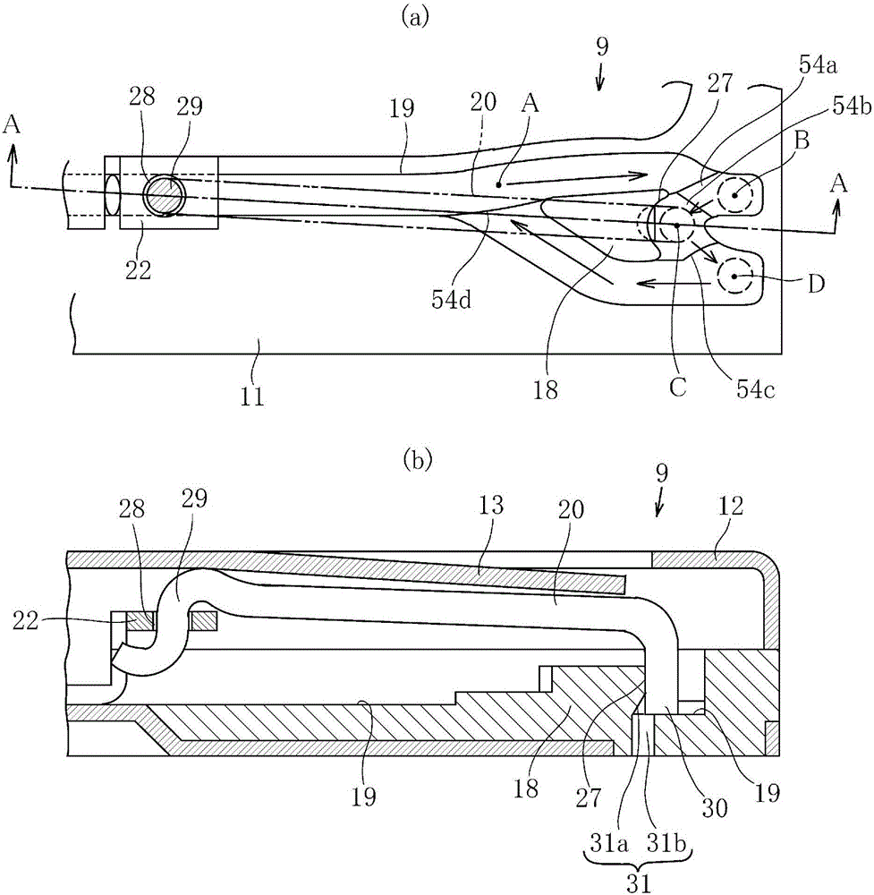
[0040] Figure 4 (a) shows the card connector 10 equipped with the heart-shaped cam locking device 9 of the present invention, and the card connector 10 has a thin plate-shaped housing 11 separated from a card insertion port 14 at the lower end in the figure to accommodate a card 15. Covered with a shield 12 . In addition, in the center of the upper surface of the card connector 10, a plurality of (in this example, 6) "へ"-shaped contacts 25 are provided at positions corresponding to the pads of the inserted card 15. The part is provided with pop-up leaf spring 26, and the right side edge part is provided with heart-shaped cam locking device 9 of the present invention in the figure.

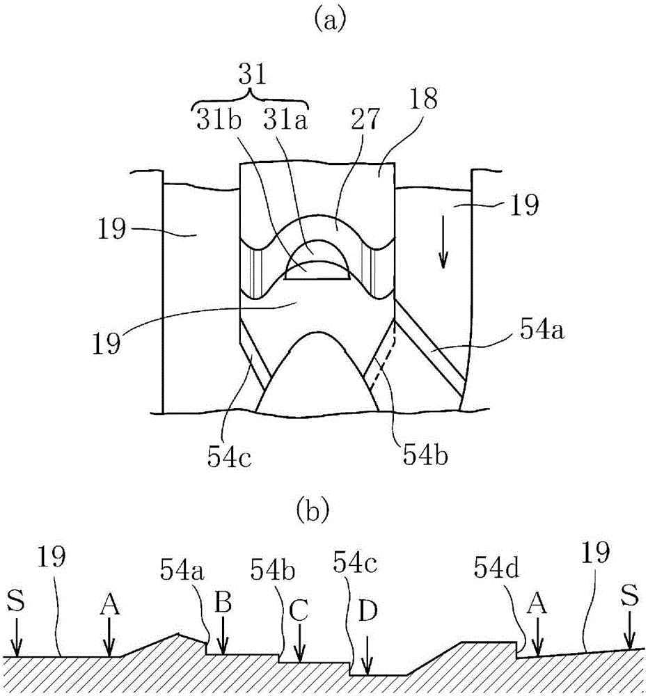
[0041] The heart-shaped cam locking device 9 is formed with a heart-shaped cam portion 18 near the upper end in the figure of the housing 11, and a sliding groove portion 19 for the locking pin 20 t...

Embodiment 2

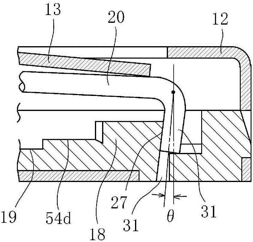
[0050] In the above-mentioned embodiment, the top engaging portion 30 of the lock pin 20 and the pin engaging concave portion 27 of the heart-shaped cam portion 18 are vertically formed, but it may also be image 3 As shown, with respect to the vertical line, the tip engaging portion 30 of the lock pin 20 and the pin engaging recess 27 of the heart-shaped cam portion 18 are slightly inclined inward at an angle θ, and formed at the lower end of the inclined pin engaging recess 27. Concave hole 31 . When adopting such a structure, the semicircular recess 31a may be eliminated and only the semicircular hole 31b may be provided, or the semicircular recess 31a and the semicircular hole 31b may be formed simultaneously.


PUM


Abstract

The invention provides a push in/out type heart-shaped cam locking device to prevent lifting of a clamp pin of a locking pin. A sliding groove portion (19) is formed on the periphery of a heart-shaped cam portion (18). When pushed in, a top clamping portion (30) of a locking pin (20) resists against and extrudes out a spring (21), slides along the outward voyage side of the sliding groove portion (19) and clamps with a pin clamp recess portion (27) of the heart-shaped cam portion (18). When pushed out, the top clamping portion (30) of the locking pin (20) resists against and extrudes out the spring (21), disconnects the clamping of the pin clamp recess portion (27), and slides along the inward voyage side. The top clamping portion (30) returns to the original position by extruding the spring (21). The heart-shaped cam locking device forms a lower end recess hole (31) for clamping the top clamping portion (30) in the lower end portion of the pin clamp recess portion (27).

Description

technical field [0001] The present invention relates to a heart cam lock device provided in a push-in / push type card connector or the like using a heart cam. Background technique [0002] The present applicant has proposed such a heart-shaped cam lock device (Patent Document 1). [0003] when based on Figure 5 ~ Figure 7 When explaining, in the Figure 7 Among them, the card connector 1 includes: a housing 3 having a card insertion portion 2 ; and a plurality of contacts (not shown) provided in the card insertion portion 2 . exist Figure 5 as well as Image 6 Among them, the card connector 1 has: an ejector 5, which moves in the housing 3 together with the card A; an extrusion spring 6; a heart-shaped cam 7; a pin guide groove 8, which is arranged around the heart-shaped cam 7; Pin 43, the engaging pin portion 4 at one end of the locking pin 43 is slidably inserted into the pin guide groove 8, and the other end of the locking pin 43 is swingably supported on the ejecti...

Claims


Application Information

Patent Timeline
IPC IPC(8): H01R13/627H01R13/635H01R12/71
CPCH01R12/714H01R13/6275H01R13/635
Inventor 德桥大辅佐佐木良
Owner SMK CO LTD
Why Eureka
Try Eureka