Casting mold and casting method for large-size disc type complicated-structure part

A technology of complex structure and parts, applied in the field of casting and casting of large-scale disc-type complex structure parts, can solve the problems of slag inclusion, shrinkage porosity, etc., and achieve the effect of stable iron feeding, prevention of shrinkage porosity, and prevention of lifting the box.

Pending Publication Date: 2018-07-31
JIANGSU JIXIN WIND ENERGY TECH
View PDF0 Cites 2 Cited by
  • Summary
  • Abstract
  • Description
  • Claims
  • Application Information

AI Technical Summary

Problems solved by technology

[0003] Therefore, in view of the technical problems in the prior art that defects such as shrinkage porosity and slag inclusion are prone to occur during the casting process of large-scale disc-type complex mechanism parts such as wind power rotors, the purpose of the present invention is to provide a casting mold for large-scale disc-type complex mechanism parts

Method used


Image

  • Casting mold and casting method for large-size disc type complicated-structure part
  • Casting mold and casting method for large-size disc type complicated-structure part
  • Casting mold and casting method for large-size disc type complicated-structure part

Examples


Embodiment 1GE

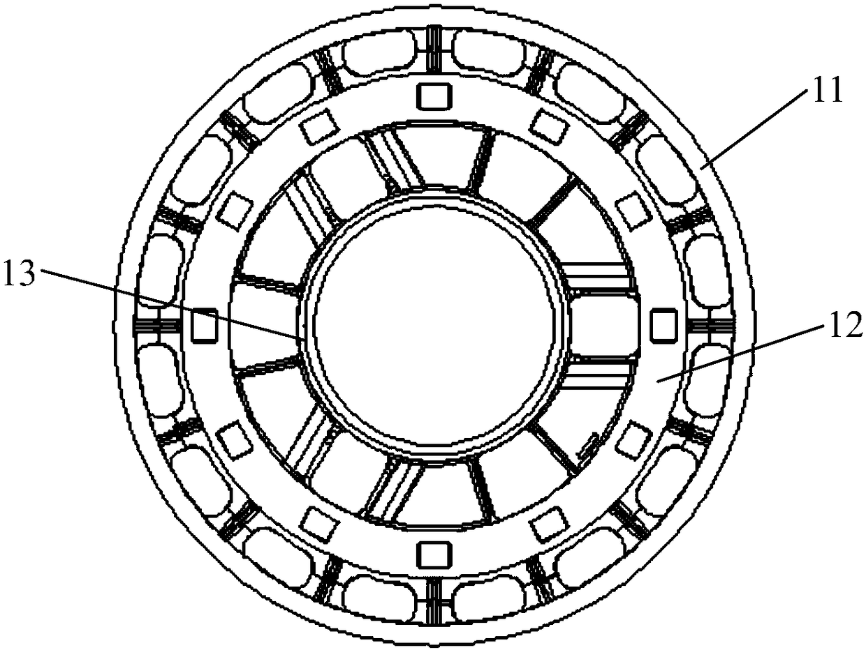
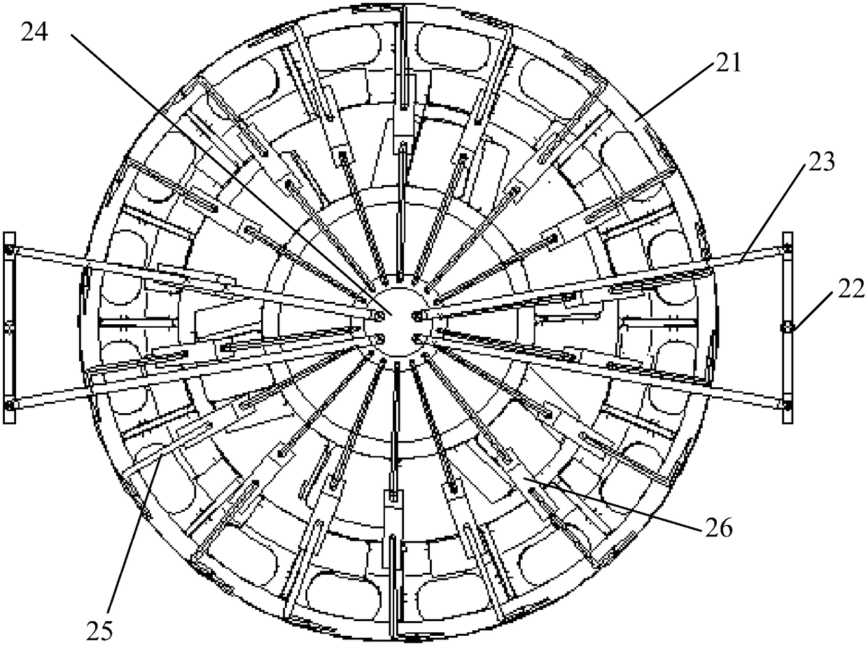
[0025] Embodiment 1 The casting mold of GE6MW rotor

[0026] The casting mold of the large-scale disk-like complex structure part (GE6MW rotor) of the preferred embodiment of the present invention includes an upper mold and a lower mold, and the manufacture of the upper mold and the lower mold can refer to the ordinary mold manufacturing method, and the sand is shaken to the sand box for molding. The cavity structure formed by clamping mold is as follows figure 2 As shown, it includes part cavity 21, riser cavity, air outlet and casting system. The shape of the component cavity 21 fits the shape of the wind power rotor (see the background technology for the specific structure). The casting system includes 2 iron inlets 22, 4 molten iron main channels 23, a central distribution cavity 24 and 18 molten iron flow channels 25. The two iron inlets are respectively arranged on both sides of the mold, and each iron inlet is correspondingly connected with two molten iron main channe...

Embodiment 2

[0028] Embodiment 2 Using the casting mold of Embodiment 1 to cast GE6MW rotor

[0029] Using the casting mold of Example 1, pour molten iron into the casting mold through the iron inlet, the casting weight is about 60T, and the casting is completed in about 200S. During the casting process, graphite chill irons are placed at positions prone to shrinkage defects, and the graphite chill iron placement positions include the outer side of the outer ring flange, the inner side of the inner ring flange, and both sides of the sheet metal. After the castings are boxed together, 18 pieces of 15T pressed iron are placed on the surface of the sand box, and the total weight of the pressed irons is about 5.7 times the weight of the casting.

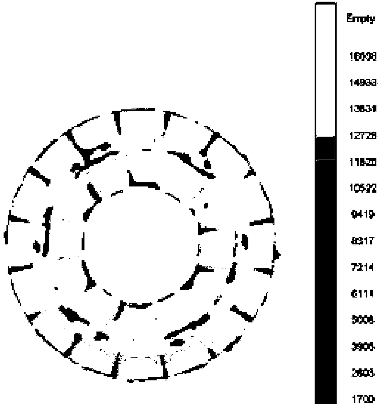
[0030] The simulation test, the steps are: use the 3D drawing software to draw the gating system, cold iron, riser, gas outlet, etc. on the casting, import it into the simulation software MAGMA, set the chemical composition, pouring temperature and o...


PUM


Abstract

The invention discloses a casting mold for a large-size disc type complicated-structure part. The casting mold comprises a casting mold body; the casting mold body is provided with a disc-like part cavity, a plurality of riser cavities, a plurality of air outlets and a grouting system; the grouting system comprises at least two iron inlets, at least two liquid iron main flow channels, a central flow dividing chamber, a plurality of liquid iron branch flow channels and a plurality of filters; the liquid iron main flow channels and the liquid iron branch flow channels are arranged at the bottomof the casting mold body; and the central flow dividing chamber is arranged at the central position of the bottom of the casting mold body. The grouting system is reasonably distributed, so the grouting time can be greatly shortened, and stable iron feeding is guaranteed. The riser cavities and the air outlets are arranged in a targeted manner in order to guarantee the air generation quantity of the cavities and shrinkage compensation of the riser. The invention also discloses a casting method, and the casting method adopts the casting mold which is combined with graphite chill iron and mold weight, thereby effectively solving the casting problems such as shrinkage, loosening, slag inclusion, cold shut and deformation which are easily generated in a casting process.

Description

technical field [0001] The invention belongs to the technical field of casting, and in particular relates to a casting mold and a casting method of large-scale disk-like complex structure parts. Background technique [0002] The large-megawatt wind power rotors used in wind turbines are large disk parts with large size and complex structure. for example figure 1 For the shown GE6MW rotor, the basic parameters are: diameter The height is 1018mm, the weight of the blank is about 47T, and the pouring weight is nearly 60T; from the outside to the inside, it includes the outer ring flange 1, the annular rib plate 2 and the inner ring flange 3, and the space between the outer ring flange 1 and the annular rib plate 2 18 vertical ribs are also connected, and 6 ribs are connected between the annular rib plate 2 and the inner ring flange 3 . The structure of other types of wind power rotors is similar to that of GE6MW rotors, and the structure is relatively complex. These parts a...

Claims


Application Information

Patent Timeline
Patent Type & Authority Applications(China)
IPC IPC(8): B22C9/24B22C9/08B22C9/02B22D27/04B22D33/06
CPCB22C9/24B22C9/02B22C9/082B22C9/086B22C9/088B22D27/04B22D33/06
Inventor 陈玉芳王卫国缪亚兵季虎唐光伟颜夕文
Owner JIANGSU JIXIN WIND ENERGY TECH
Why Eureka
Try Eureka