Ultrasonic motor with multiple axially laminated stators

An ultrasonic motor and multi-stator technology, which is applied to piezoelectric effect/electrostrictive or magnetostrictive motors, generators/motors, electrical components, etc., can solve the problems of single structure and difficult expansion of ultrasonic motors, and achieve Effects of improving frictional driving ability, improving working life and reliability, and high energy efficiency utilization

Inactive Publication Date: 2017-03-22
SHENZHEN UNIV
View PDF5 Cites 5 Cited by
  • Summary
  • Abstract
  • Description
  • Claims
  • Application Information

AI Technical Summary

Problems solved by technology

[0008] Aiming at the above technical problems, the present invention discloses an ultrasonic motor with multi-stators axially stacked, which is easy to stack the stators in the axial direction to form a large torque output, and forms a plurality of motor array drives to meet the application requirements of specific occasions; solve the problem of existing ultrasonic motors The structure is single and not easy to expand

Method used


Image

  • Ultrasonic motor with multiple axially laminated stators
  • Ultrasonic motor with multiple axially laminated stators
  • Ultrasonic motor with multiple axially laminated stators

Examples


Embodiment 1

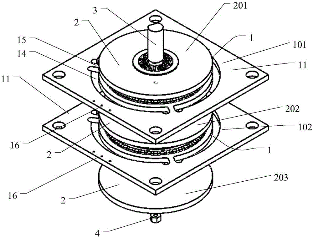
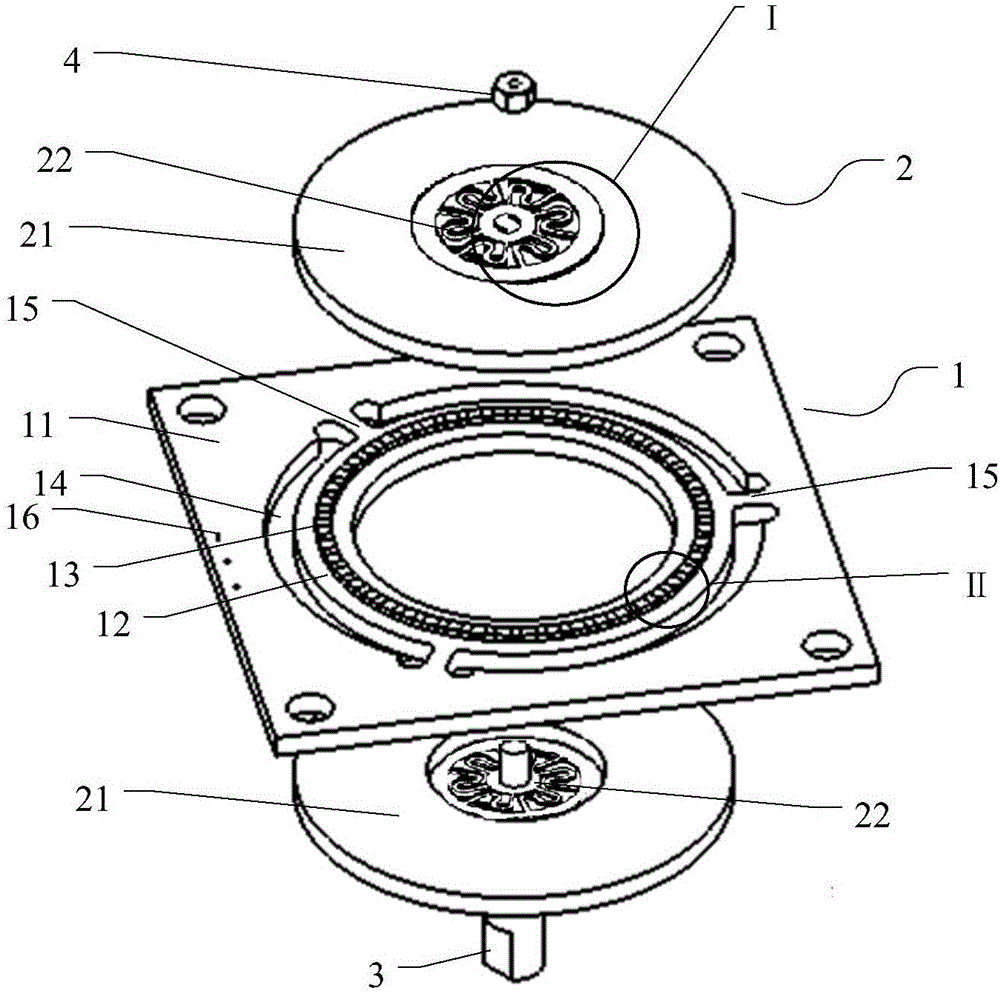
[0054] Such as Figure 1~Figure 4 As shown, an ultrasonic motor with axially laminated multiple stators includes a stator 1, a rotor 2 and an output shaft 3. The number of the stator 1 is two, the number of the rotor 2 is three, and the output The shaft 3 is one; the rotor 2 and the stator 1 are stacked in sequence. The rotor 2 includes a first rotor 201, a second rotor 202, and a third rotor 203; the stator 1 includes a first stator 101 and a second rotor. Two stators 102, the output shaft 3 passes through the first rotor 201, the first stator 101, the second rotor 202, the second stator 102, and the third rotor 203 in sequence, and then is fixedly connected with the nut 4, and the stator 1 drives the rotor 2 Rotation forms power output; each stator 1 corresponds to two rotors 2, and the middle rotor 2 is shared by the second rotor 202, that is, it is connected to the first stator 101 above and the second stator 102 below it.

[0055] Each stator 1 includes a hollow stator plat...

Embodiment 2

[0065] On the basis of embodiment 1, this embodiment is different from embodiment 1 in that the four-phase driving method is adopted. The arrangement rule and signal connection method of piezoelectric ceramic elements 13 on the stator ring 12 on the pads are different from those in embodiment 1. Specifically:

[0066] Such as Image 6 As shown, the piezoelectric ceramic element 13 and the electrodes include 4 sets of standing wave driving units, namely unit a, unit b, unit c, and unit d, each unit includes two piezoelectric ceramic elements on the front of the stator ring 12 13 and the two piezoelectric ceramic elements 13 on the reverse side of the stator ring 12, the piezoelectric ceramic elements 13 are arranged in sequence according to unit a, unit b, unit c, and unit d, and are cyclically arranged on the front and back surfaces of the stator ring 12;

[0067] In the unit a, unit b, unit c, and unit d, the polarized positive poles 131 of the two piezoelectric ceramic elements 1...


PUM


Abstract

The invention provides an ultrasonic motor with multiple axially laminated stators. The ultrasonic motor comprises at least two stators, a rotor and an output shaft, wherein each stator comprises a hollow stator plate and a piezoelectric ceramic module; a hollow stator ring is arranged in the middle of each stator plate; bonding pads in annular distribution are arranged on each stator ring; each piezoelectric ceramic module comprises N piezoelectric ceramic elements; the piezoelectric ceramic elements are welded and fixed on the bonding pads of each stator ring; a gap for vibration of each stator ring is arranged between each stator plate and the corresponding stator ring; each stator ring is connected with the corresponding stator plate through a connector; the rotor is in contact with the surfaces of the piezoelectric ceramic modules, an output shaft passes through the middle parts of the sequentially laminated rotor and stator rings to be connected; and the stators drive the rotor to rotate to form power output. According to the ultrasonic motor, the stators are axially laminated to form high torque output, the energy efficiency utilization rate is high and the electromechanical conversion efficiency is high.

Description

Technical field [0001] The invention belongs to the technical field of motors, and particularly relates to an ultrasonic motor with axially laminated multiple stators. Background technique [0002] Ultrasonic motor is a non-electromagnetic motor that uses the inverse piezoelectric effect of piezoelectric ceramics to excite the stator to vibrate in the ultrasonic frequency domain, and converts the vibration into the motion of the rotor through the friction between the stator and the rotor to drive the load. Compared with electromagnetic motors, it has the characteristics and advantages of small size, light weight, compact structure, fast response, low noise, no electromagnetic interference, high torque density, low speed and high torque, and direct drive. At present, it has been used in many fields such as micro robots, automobiles, aerospace, precision positioners, and optical instruments, and has broad application prospects. Traveling wave rotary ultrasonic motor is currently t...

Claims


Application Information

Patent Timeline
Patent Type & Authority Applications(China)
IPC IPC(8): H02N2/12H02N2/14H02N2/16
CPCH02N2/12H02N2/14H02N2/163
Inventor 彭太江伍晓宇石鸿雁梁雄罗峰徐斌
Owner SHENZHEN UNIV
Why Eureka
Try Eureka