Loudspeaker and audio equipment
A loudspeaker and sound film technology, which is applied in the direction of loudspeakers, sensors, electrical components, etc., can solve the problems of high-frequency sensitivity, low-frequency sensitivity, and low-frequency sensitivity of the speaker, and achieve the effect of improving low-frequency sensitivity
- Summary
- Abstract
- Description
- Claims
- Application Information
AI Technical Summary
Problems solved by technology
Method used
Image
Examples
Embodiment 1
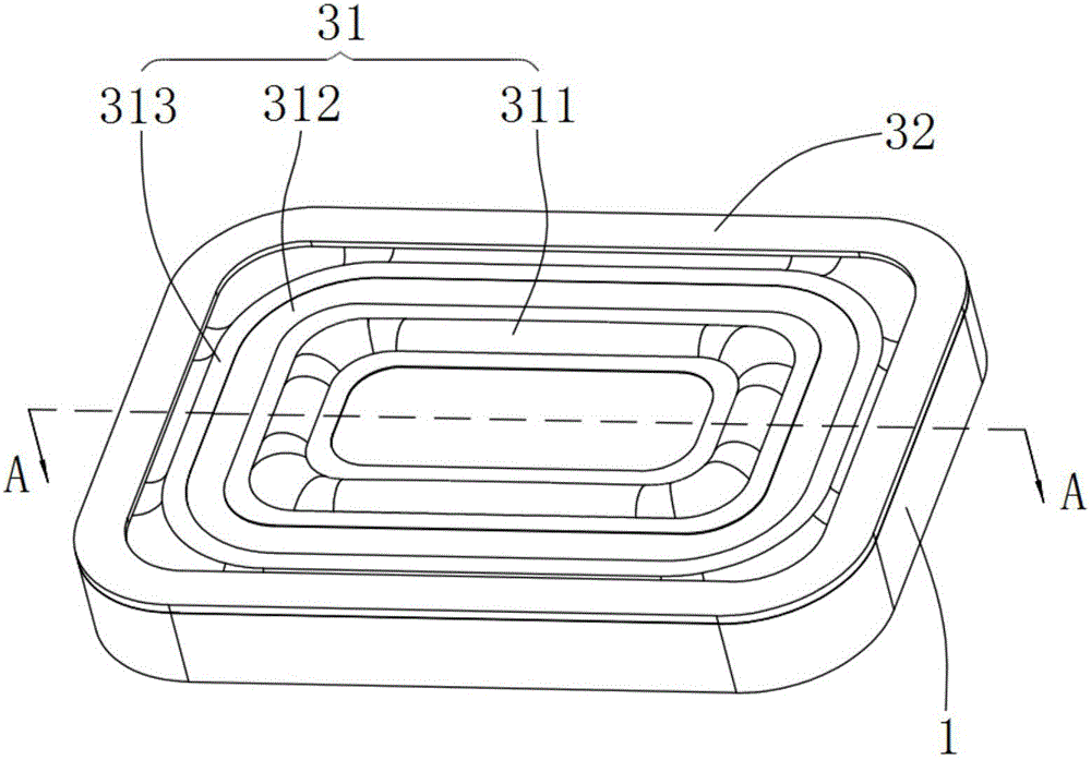
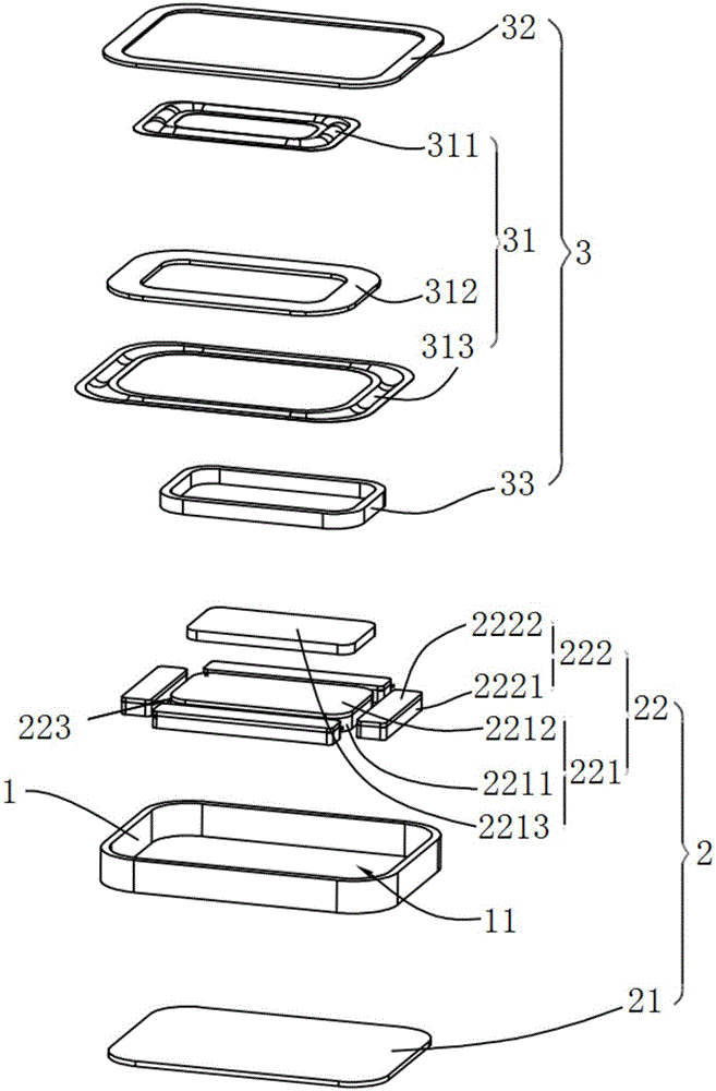
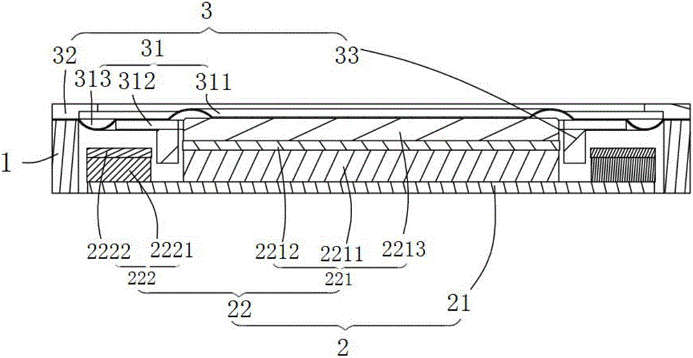
[0055] This embodiment provides a speaker, such as Figure 1 to Figure 3 As shown, the speaker of this embodiment includes: a basin frame 1 , a magnetic circuit system 2 and a vibration system 3 . Wherein, the basin frame 1 has a receiving space 11 ; the magnetic circuit system 2 and the vibration system 3 are all accommodated in the receiving space 11 of the basin frame 1 . Wherein, the magnetic circuit system 2 is connected with the vibration system 3, so that the magnetic circuit system 2 can drive the vibration system 3 to vibrate and sound, and at the same time, the vibration system 3 can drive the magnetic circuit system 2 to vibrate.
[0056] The loudspeaker in this embodiment makes the vibrating system 3 vibrate and produce sound under the drive of the magnetic circuit system 2 through the above arrangement, so that the mid-high frequency sensitivity of the loudspeaker is high. At the same time, the vibration system 3 can drive the magnetic circuit system 2 to vibrate...
Embodiment 2
[0061] Preferably, this embodiment provides a loudspeaker, compared with the previous embodiment, such as figure 2 and image 3As shown, the magnetic circuit system 2 in the speaker of this embodiment includes a magnetic bowl 21 and a magnet part 22 . Wherein, the magnetic bowl 21 is arranged in the accommodation space of the basin frame 1 . Preferably, the magnetic bowl 21 is a flat structure. The magnet part 22 is provided on the magnetic bowl 21 . Wherein, the magnet part 22 includes a first magnet part 221 and a plurality of second magnet parts 222 . A plurality of second magnet parts 222 are disposed around the first magnet part 221 . And there is a magnetic gap 223 between the second magnet part 222 and the first magnet part 221 .
[0062] Preferably, if figure 2 and image 3 As shown, the first magnet part 221 in the magnetic circuit system 2 in this embodiment includes: a first main magnet 2211 , a main pole core 2212 and a second main magnet 2213 . Wherein, ...
Embodiment 3
[0066] Preferably, this embodiment provides a loudspeaker, compared with the previous embodiment, such as Figure 1 to Figure 3 As shown, the vibration system 3 in this embodiment includes: a sound membrane 31 and a voice coil 33 . Wherein, the sound membrane 31 is arranged in the receiving space 11 of the frame 1 and connected with the frame 1 . The voice coil 33 is disposed opposite to the magnetic bowl 1 , and the voice coil 33 is spaced apart from the magnetic bowl. One end of the voice coil 33 is inserted into the magnetic gap 223 , and the other end is connected to the sound membrane 31 for driving the sound membrane 31 to vibrate.
[0067] Preferably, if figure 2 and image 3 As shown, the sound membrane 31 includes: a first ring 311 , a dome 312 and a second ring 313 . Wherein, the first ring 311 is located in the middle of the sound membrane 31 . The second ring 313 is located at the edge of the sound membrane 31 . The dome 312 connects the first ring 311 and t...
PUM
 Abstract
Description
Claims
Application Information
 - R&D
- Intellectual Property
- Life Sciences
- Materials
- Tech Scout
- Unparalleled Data Quality
- Higher Quality Content
- 60% Fewer Hallucinations
Browse by: Latest US Patents, China's latest patents, Technical Efficacy Thesaurus, Application Domain, Technology Topic, Popular Technical Reports.
© 2025 PatSnap. All rights reserved.Legal|Privacy policy|Modern Slavery Act Transparency Statement|Sitemap|About US| Contact US: help@patsnap.com


