Acoustic device and electronic apparatus

a technology of electronic equipment and acoustic device, which is applied in the field of acoustics, can solve the problems of affecting the acoustic performance of the loudspeaker unit, the the miniature acoustic system is difficult, so as to achieve the effect of reducing the resonance frequency and improving the sensitivity

Pending Publication Date: 2022-03-03
GOERTEK INC
View PDF7 Cites 0 Cited by
  • Summary
  • Abstract
  • Description
  • Claims
  • Application Information

AI Technical Summary

Benefits of technology

[0003]An object of the present invention is to provide an acoustic device which can effectively reduce the r...

Problems solved by technology

Due to the volume limitation of the cavity in the acoustic system, it is difficult for the acoustic systems, especially the miniature acoustic system, to achieve the effect of reproducing the bass satisfactorily.
However, there are some defects in the two ways mentioned above.
The first way of adding sound absorption materials into the box needs to achieve a good sealing package of sound absor...

Method used


Image

  • Acoustic device and electronic apparatus
  • Acoustic device and electronic apparatus
  • Acoustic device and electronic apparatus

Examples


embodiment 1

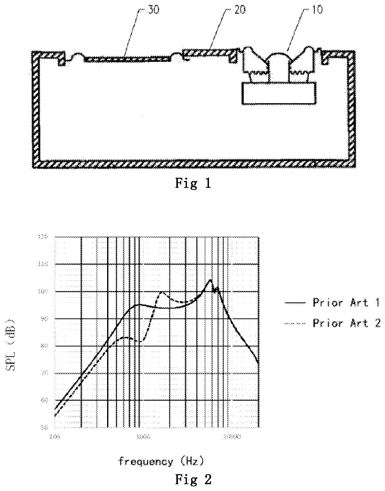
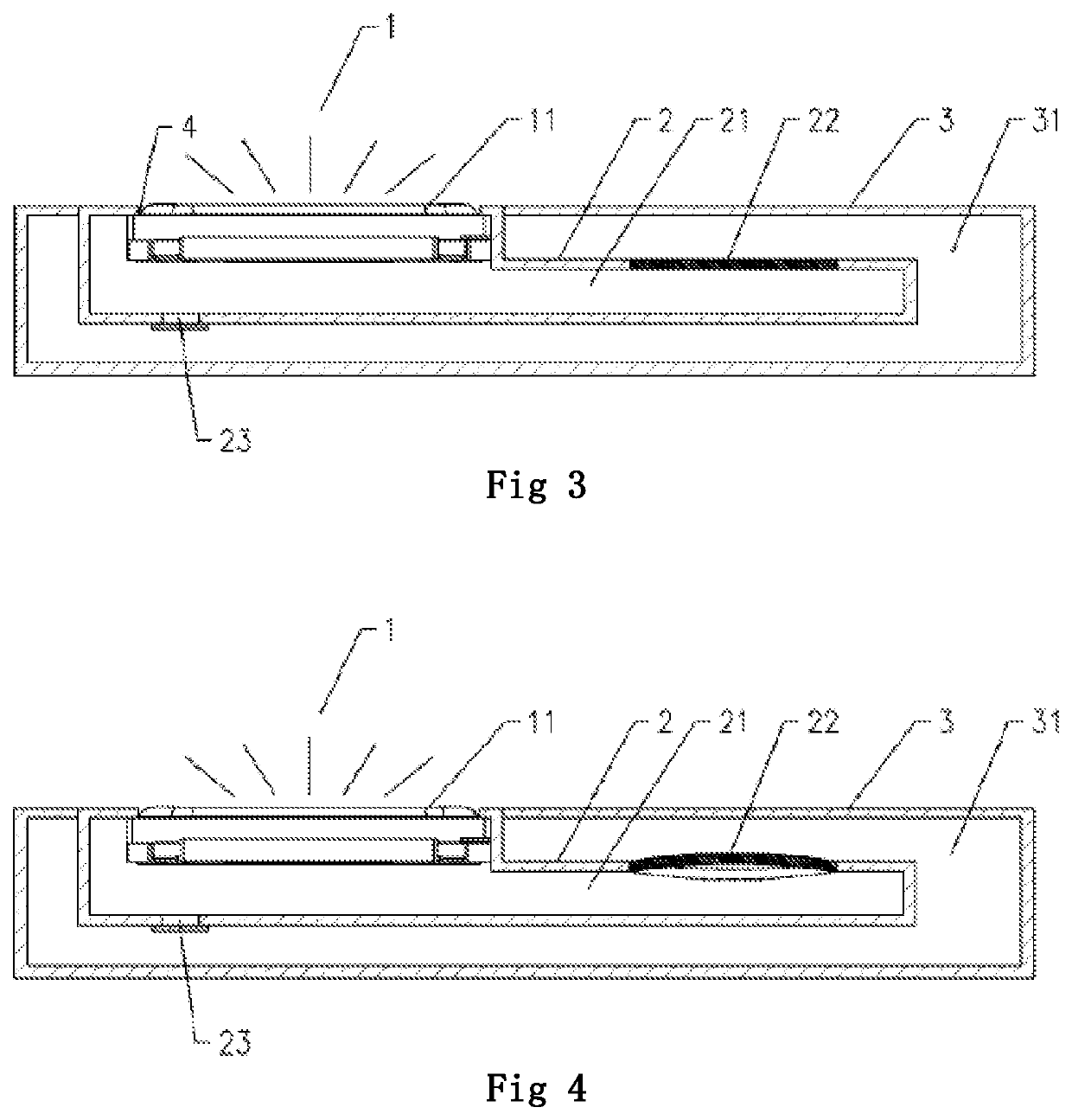
[0047]As shown in FIG. 3, an acoustic device comprises a sound generating unit 1. In this embodiment, the sound generating unit 1 is a micro sound generating unit, and more specifically, the sound generating unit 1 is a micro moving coil loudspeaker. The sound generating unit 1 generally comprises a housing, and a vibration system and a magnetic circuit system which are accommodated and fixed in the housing. The vibration system comprises a vibration diaphragm 11 fixed on the housing and a voice coil coupled on the vibration diaphragm 11. The magnetic circuit system is provided with a magnetic gap, and the voice coil is provided in the magnetic gap. The voice coil reciprocates up and down in the magnetic field after the alternating current is applied to the voice coil, and thus driving the vibration diaphragm 11 to vibrate and generate sound.

[0048]The acoustic device is provided with a sound outlet 4, the sound waves at the front side of the vibration diaphragm 11 is radiated to the...

embodiment 2

[0068]As shown in FIG. 7, the main difference between this embodiment and the embodiment 1 is that the flexible deformation part 22 in this embodiment is an independent mounting part, and a through-hole is provided on an isolation part (not shown), and the flexible deformation part 22 is mounted on the through-hole. Specifically, the flexible deformation part 22 is fixedly connected with the portion of the first housing around the through-hole by means of bonding, welding or hot melting. Such an improved design is more convenient in the material selection of the flexible deformation part 22, and can realize a more practical combination with the first housing. Meanwhile, providing the through-hole on the first housing may simplify the product process.

embodiment 3

[0069]The main difference between this embodiment and the above embodiments is that the acoustic device in this embodiment is provided with a sound channel, and the sound channel is designed to correspond to the sound outlet 4, and the sound waves at the front side of the vibration diaphragm 11 radiates to the sound outlet 4 through the sound channel. This design furthermore meets the design requirements for some terminal products, may not occupy the space of the panels such as mobile phone, is benefit to the design of full screen, and can avoid the blocking and interfering from other components.

[0070]Specifically, as shown in FIG. 8, the sound generating unit 1 is mounted in the first housing 2, and the sound channel is also provided on the first housing 2. In other embodiments, the sound channel may be provided on the second housing 3, and the sound generating assembly may be opposed to and coupled with the sound channel; or the sound channel may be provided separately, and the so...


PUM


Abstract

An acoustic device comprises a sound generating unit having a vibration diaphragm, the acoustic device is provided with a sound outlet, the sound waves at a front side of the vibration diaphragm radiates to the outside through the sound outlet; and an enclosed closed cavity formed at a rear side of the vibration diaphragm, the closed cavity is divided into first and second closed cavities by a partition part, and at least a portion of the partition part flexibly deforms, the first closed cavity is adjacent to the vibration diaphragm, the second closed cavity is far away from the vibration diaphragm, the volume of the second closed cavity is larger than that of the first closed cavity; the second closed cavity encloses the sound into the second closed cavity; at least a part of an electronic apparatus housing is used for forming the first and/or the second closed cavity.

Description

TECHNICAL FIELD[0001]The present disclosure relates to the technical field of acoustics, and more particularly, to an acoustic device and an electronic apparatus in which the acoustic device is mounted.BACKGROUND ART[0002]In general, an acoustic system with a traditional structure (Prior Art 1) includes a closed box and a sound generating unit disposed on the closed box, and a cavity is formed between the closed box and the sound generating unit. Due to the volume limitation of the cavity in the acoustic system, it is difficult for the acoustic systems, especially the miniature acoustic system, to achieve the effect of reproducing the bass satisfactorily. Conventionally, in order to achieve satisfactory bass reproduction in an acoustic system, two ways are usually used: one way is to provide sound absorption materials (such as activated carbon, zeolite, etc.) in the box of the acoustic system to absorb or desorb the gas in the box, so as to increase the volume and therefore reduce t...

Claims


Application Information

Patent Timeline
IPC IPC(8): H04R1/28H04R9/06H04R7/04
CPCH04R1/2842H04R2499/11H04R7/04H04R9/06H04R7/06H04R1/22H04R1/2834H04R1/30H04R1/2869H04R9/02
Inventor LIU, CHUNFAXU, TONGYANZHANG, CHENGFEI
Owner GOERTEK INC
Why Eureka
Try Eureka