

Acceleration sensor and method for operating an acceleration sensor
- Summary
- Abstract
- Description
- Claims
- Application Information
AI Technical Summary
Benefits of technology
Problems solved by technology
Method used
Image

Examples
Embodiment Construction
[0040]In the various figures, identical parts have been provided with the same reference symbols and are therefore usually labeled or mentioned only once.
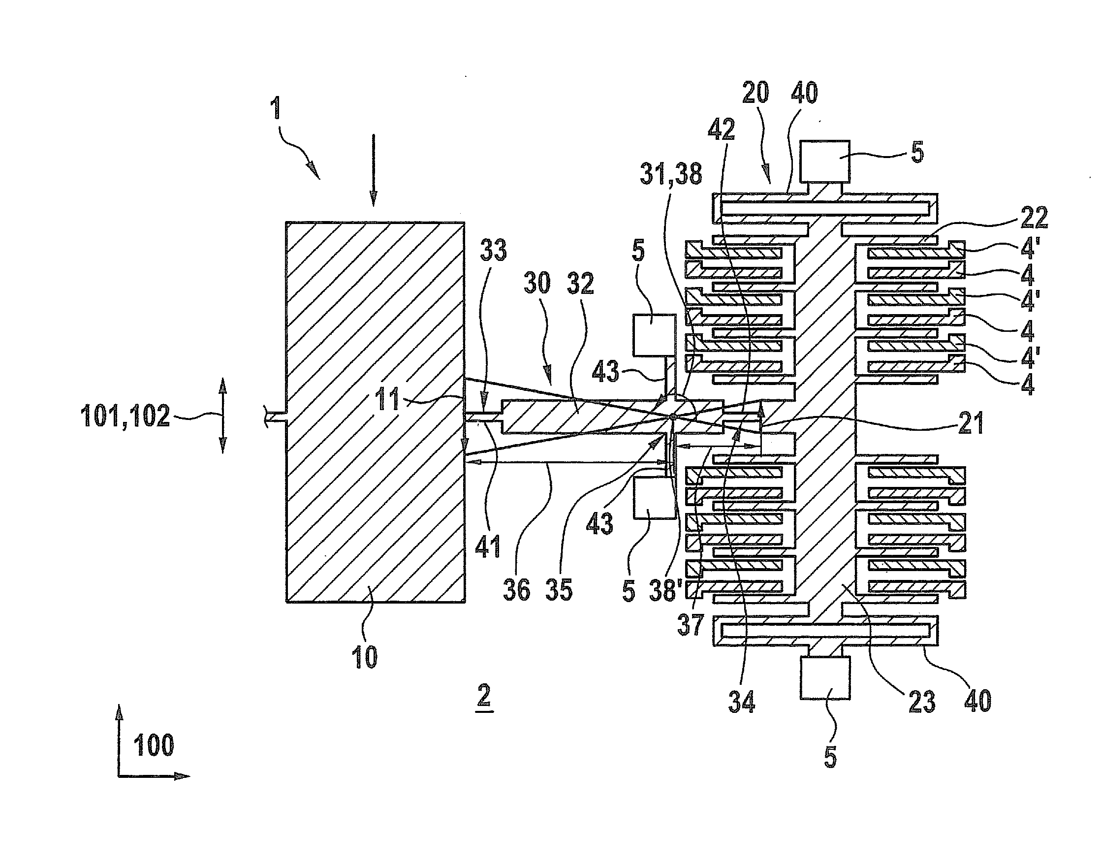
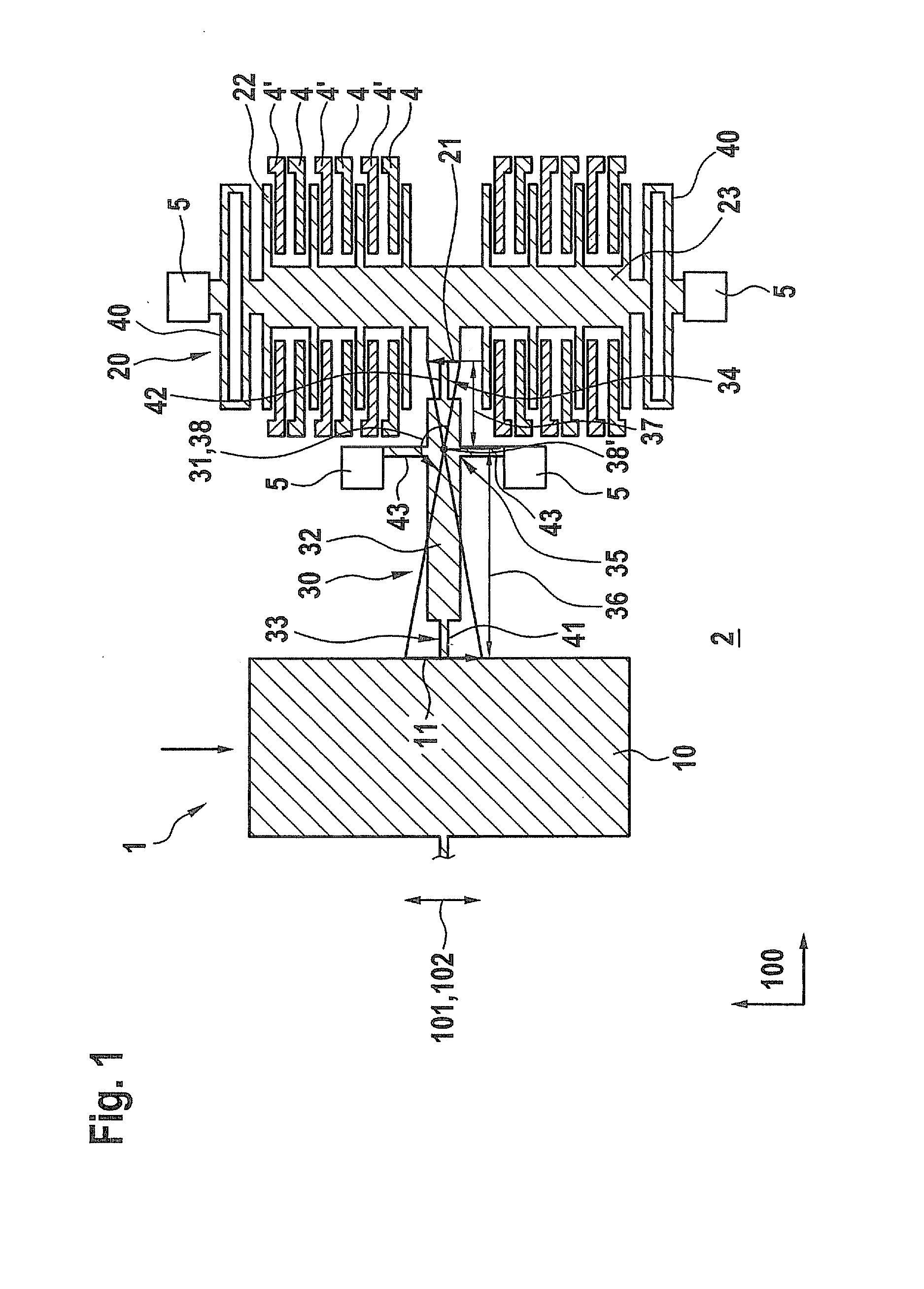
[0041]FIG. 1 shows a schematic view of an acceleration sensor 1 according to a first specific embodiment of the present invention. Acceleration sensor 1 includes, for example, a MEMS (microelectro mechanical system) component having a substrate 2 made of a semiconductor material, preferably silicon. Furthermore, acceleration sensor 1 has a seismic mass 10 and a detection unit 20. Substrate 2 preferably has been patterned appropriately in a standard semiconductor production process, particularly within the scope of a lithography, etching, deposition and / or bonding method, so as to develop seismic mass 10, as well as detection unit 20. Seismic mass 10 is deflectable with respect to substrate 2 within the scope of a deflection motion 11. Deflection motion 11 takes place along a deflection direction 101, which extends parallel to a mai...
PUM
 Abstract
Description
Claims
Application Information