Automated system and method for probe measurement of stack gas flow properties

Active Publication Date: 2009-12-01
AIRFLOW SCI LEASING
View PDF31 Cites 2 Cited by
  • Summary
  • Abstract
  • Description
  • Claims
  • Application Information

AI Technical Summary

Benefits of technology

[0015]Accordingly, the present invention is directed toward an automated measuring probe having a number of features that contribute to greater robustness, to improved accuracy, ease of use, and the ability to position a larger probe over a greater distance with acceptable droop.

Problems solved by technology

Some aspects of the patented probes that may compromise robustness include: translational accuracy of the probe; the use of spring washers in one version to force the roller wheels against the probe wall in the apparent interest of providing adequate cantilever support, but at the same time creating additional stresses that must be accommodated by mechanical strengthening, which typically means added mass, and motor size large enough not only to move the probe but in doing so to also overcome the opposing force components of the spring washers; and the use of two housings, one within another, adding complexity and weight.

Method used


Image

  • Automated system and method for probe measurement of stack gas flow properties
  • Automated system and method for probe measurement of stack gas flow properties
  • Automated system and method for probe measurement of stack gas flow properties

Examples


Embodiment Construction

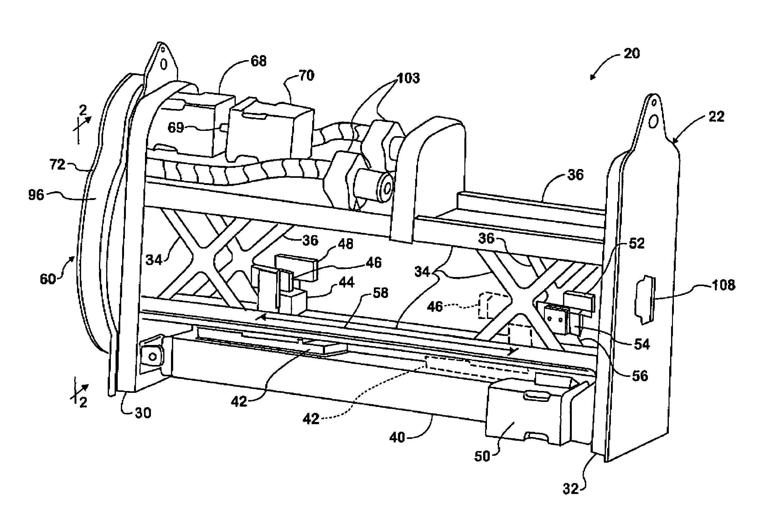
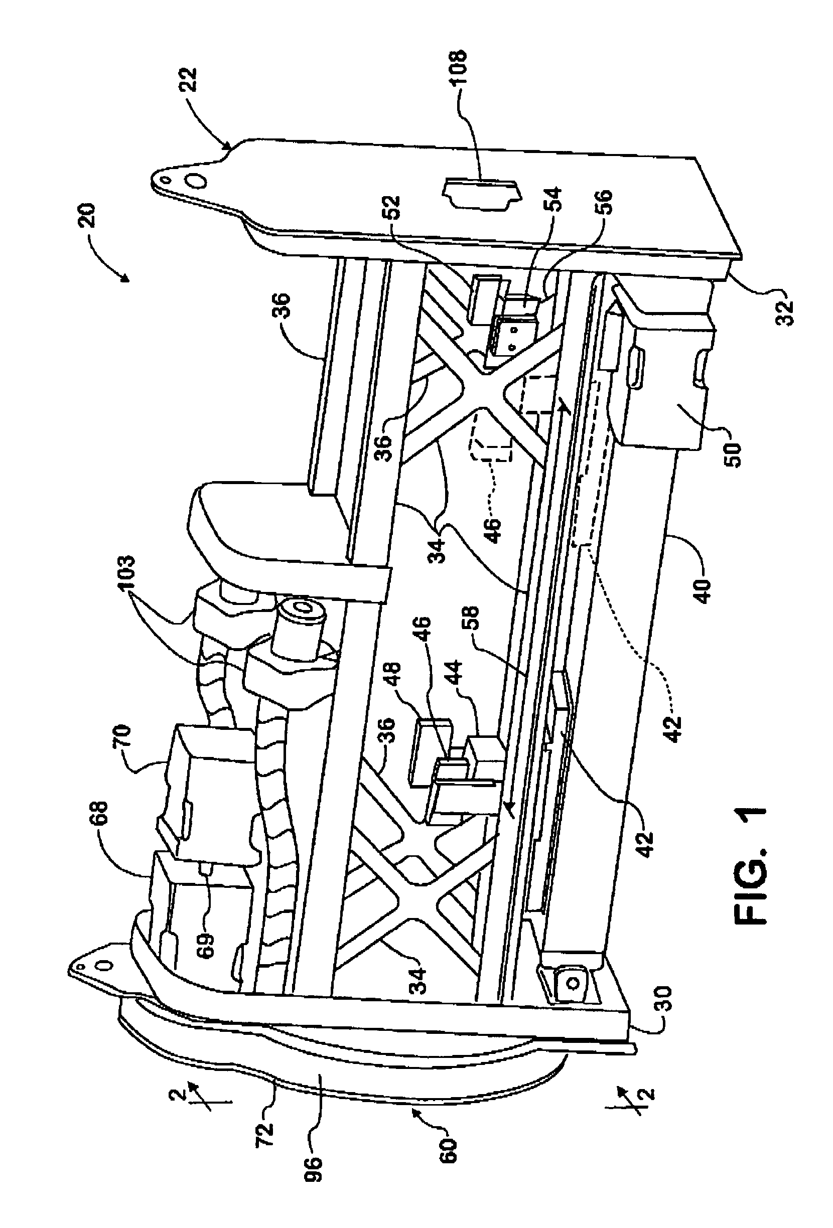
[0033]For automating any of various known types of sensing tips, the invention provides an automated probe 20 comprising a self-contained supporting and positioning mechanism for supporting and positioning a square tube at one end of which a sensing tip is mounted. Probe 20 is adapted for mounting on a stack at a test port of the stack that is designed to allow the probe to be separably fastened to it, thereby supporting the entire probe 20 (including the probe assembly when the probe assembly is in place) on the stack. The probe assembly (to be more fully described later) comprises a square tube and a sensing tip that is compliant with 40 CFR for performing flow velocity measurements, with the sensing tip being fastened to one end of the square tube. The probe 20 can position the probe assembly in two directions, one being translationally across the stack diameter and the other being rotationally about the centerline of the probe assembly.

[0034]The automated probe 20 is arranged an...


PUM


Abstract

A system and method for the automated measurement of properties related to a stack gas stream, flow velocity for example. A probe assembly (24) is introduced into a stack through a test port and operated by an automated mechanism mounted on the test port to position a sensing tip (28) at various locations within the gas stream at proper yaw angle. A framework (30, 32, 34, 36) of the automated mechanism provides bearing support for the probe assembly while allowing the probe assembly to translate on the framework along an axis but constraining the probe assembly from turning on the framework about the axis. With a gripper assembly (44) gripping the probe assembly and another gripper assembly (56) released, a linear actuator (40) can move the gripper assembly (44) along the axis to translate the probe assembly on the framework. A motor (70), also mounted on the framework, can turn a pinion (66) that is in mesh with a toothed segment (64) of a ring gear (62) that attaches to the stack port so that the motor (70) can turn the framework and probe assembly together about the axis.

Description

FIELD OF THE INVENTION[0001]This invention relates to a system and method for the automated measurement of properties related to a stack gas stream, flow velocity for example, using a probe that is introduced into a stack through a test port and operated to position a sensing tip at various locations within the gas stream at proper yaw angle.BACKGROUND OF THE INVENTION[0002]Industrial emissions to the atmosphere, such as those from powerplants that combust fossil fuels to generate electricity, are subject to governmental regulation that is enforced by the United States Environmental Protection Agency (EPA).[0003]Pursuant to statutory authority, the EPA has promulgated regulations that are embodied in portions of the Code of Federal Regulations (CFR). Included in portions of 40 CFR are regulations pertaining to measurement of volumetric flow rate of stack gas streams. While the regulations specify acceptable methods of measurement and types of probes that are introduced into stacks t...

Claims


Application Information

Patent Timeline
IPC IPC(8): G01D21/00
CPCG01F1/46G01N35/08
Inventor FLEMING, MATTHEW M.DEVLIN, BRUCE R.GENTRY, MATTHEW R.
Owner AIRFLOW SCI LEASING
Why Eureka
Try Eureka