
Human-body infrared induction device

An induction device and human body infrared technology, applied in the field of infrared detection, can solve the problems of switching peripherals, inability to detect human body infrared radiation signals, frequent delays, etc., to improve reliability, reduce complexity, improve accuracy and use convenience effect

Pending Publication Date: 2017-06-20
SHENZHEN MEISI XIANRUI ELECTRONICS CO LTD
View PDF9 Cites 4 Cited by
  • Summary
  • Abstract
  • Description
  • Claims
  • Application Information

AI Technical Summary

Problems solved by technology

Due to the uncertainty of lighting time, automatic door opening time, faucet running time, etc. required by people's activities in specific actual scenarios, and the delay parameter of the delay control chip depends entirely on the size of the delay capacitor, so the pyroelectric infrared human body Once the sensor module is installed, it is difficult to adjust the delay parameters. If the delay is too long, it is not conducive to energy saving, environmental protection and automatic control. If the delay is too short, it is easy to switch peripherals frequently, which will cause inconvenience to people's activities and affect the working life of peripherals.
At the same time, the pyroelectric infrared human body sensing module also needs to be equipped with a bright and dark field Fresnel lens chopper device to generate an alternating "blind zone" and "visible zone" in front of the sensor. The emitted infrared radiation will be intermittently received by the pyroelectric element, so that the polarity of its charge is continuously switched, and a pulse signal can be output, so it cannot detect the infrared radiation signal of the human body that is still or has a small range of motion.

Method used


Image

  • Human-body infrared induction device
  • Human-body infrared induction device
  • Human-body infrared induction device

Examples


Embodiment 1

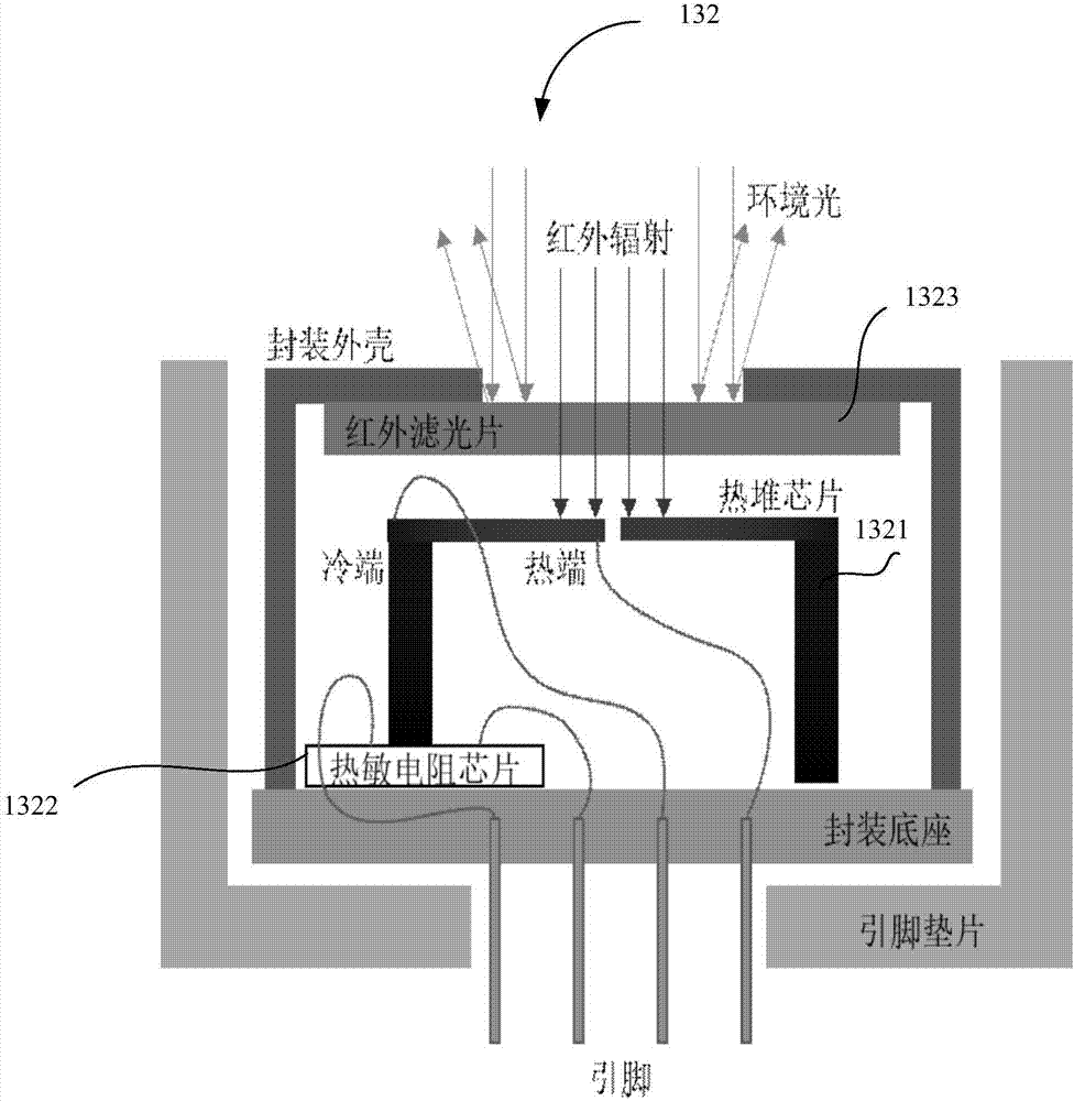
[0044] The first way is as Figure 5 , using 5V DC power supply, the power adapter interface can choose the standard microUSB female port to facilitate power supply; when there is an infrared radiation signal in the sensing area, the thermopile chip absorbs heat to generate thermal electromotive force, and outputs a small output from the 1 and 3 pins of the Sensor Voltage signal V total , V total The RC circuit composed of R1 and C1, R2 and C2 initially filters out the high-frequency noise signal, and then filters out the common-mode noise signal through the IC1 chip, and at the same time, the output voltage is g after the operational amplification of IC1 1 *V total , the magnification g1 is determined by R2 / R1; the divided voltage signal V of the thermistor NTC Output from pins 2 and 4 of Sensor, through the RC circuit composed of R7 and C5, after preliminarily filtering out the high-frequency noise signal, IC2 controls g 1 *V total and V NTC Carry out differential comp...

Embodiment 2

[0046] The first way is as Image 6 , the difference from Embodiment 1 is that the relay is powered by a 12V DC power supply, and the power adapter interface can be a standard 3.5mm power female port, which is suitable for use scenarios of high-power external devices, and will not be repeated here.


PUM


Abstract

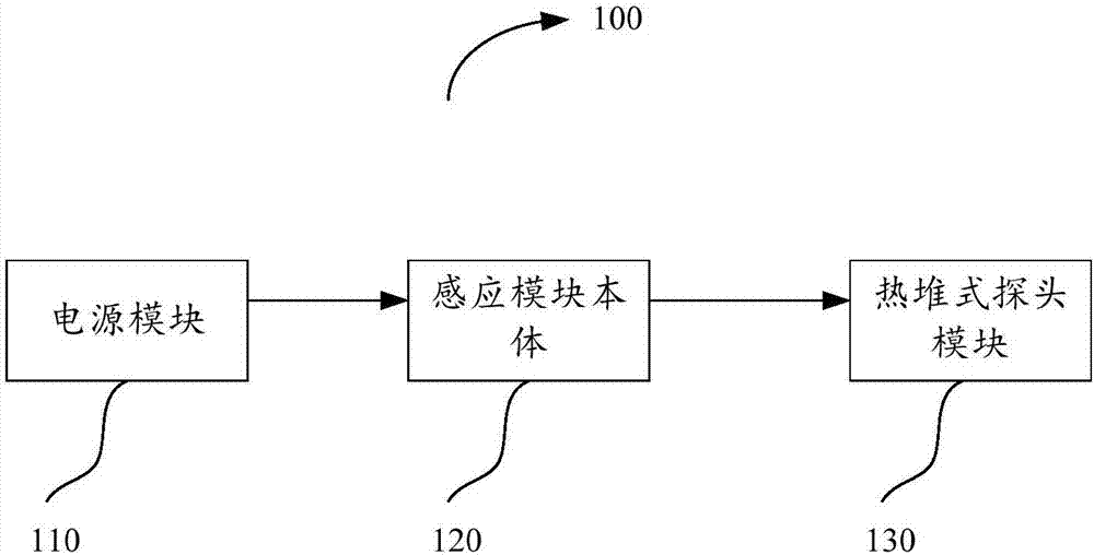
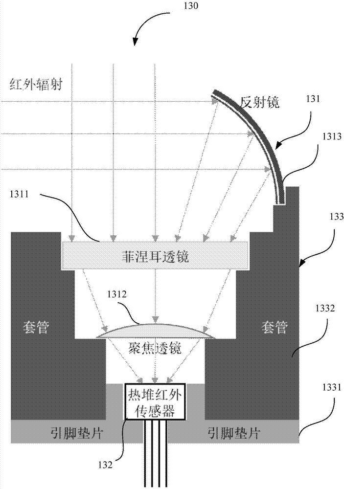
The invention provides a human-body infrared induction device. A thermopile chip converts infrared radiation energy of the human body into a continuously output voltage signal, a thermistor chip forms a voltage dividing signal in a circuit loop, an induction module body processes the voltage signal and the voltage dividing signal, whether the thermopile chip and the thermistor chip include a temperature difference caused by infrared radiation is calculated according to the voltage signal and the voltage dividing signal, and whether the human body exists in the surrounding is determined. Use of a time-delay control chip of low flexibility and pre-estimation of a time delay parameter are avoided, the human body induction accuracy and the using convenience are improved, a bright / dark-field Fresnel lens chopping device is not needed, the complex degree of the module is reduced, and the reliability is improved.

Description

technical field [0001] The invention relates to the technical field of infrared detection, in particular to a human body infrared sensing device. Background technique [0002] In the traditional pyroelectric infrared human body sensing module, a delay control chip is usually used to realize the continuous operation of lamps, automatic doors and other peripherals within a certain continuous period of time. Due to the uncertainty of lighting time, automatic door opening time, faucet running time, etc. required by people's activities in specific actual scenarios, and the delay parameter of the delay control chip depends entirely on the size of the delay capacitor, so the pyroelectric infrared human body Once the sensor module is installed, it is difficult to adjust the delay parameters. If the delay is too long, it is not conducive to energy saving, environmental protection and automatic control. If the delay is too short, it is easy to switch peripherals frequently, which will...

Claims


Application Information

Patent Timeline
IPC IPC(8): G01J5/12G01J5/20G01V8/10
CPCG01J5/12G01J5/20G01V8/10G01J2005/123
Inventor 武斌郑星宇张绍达
Owner SHENZHEN MEISI XIANRUI ELECTRONICS CO LTD
Learn More