

Fluidic rotor having orientable blades with improved blade control
- Summary
- Abstract
- Description
- Claims
- Application Information
AI Technical Summary
Benefits of technology
Problems solved by technology
Method used
Image

Examples
Embodiment Construction
[0033]Throughout the present description, reference shall be made to the rotor as described in application WO2014 / 006603A1, the contents of which shall be deemed to form part of the present description. The contents of application WO2016 / 067251A1 in the name of the Applicant shall also be deemed to form part of the present description.
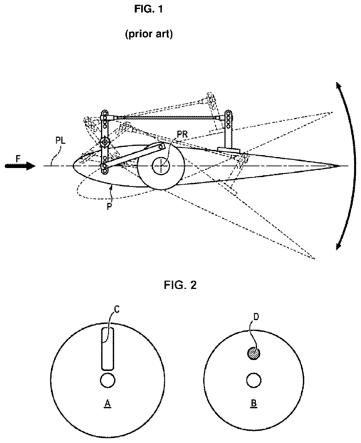
[0034]With reference firstly to FIG. 1, from the perspective of plane PL of a rotor blade P (in relation to the direction F of the flow of gas or liquid), the movement is an oscillating movement about a point of rotation PR located on the blade.
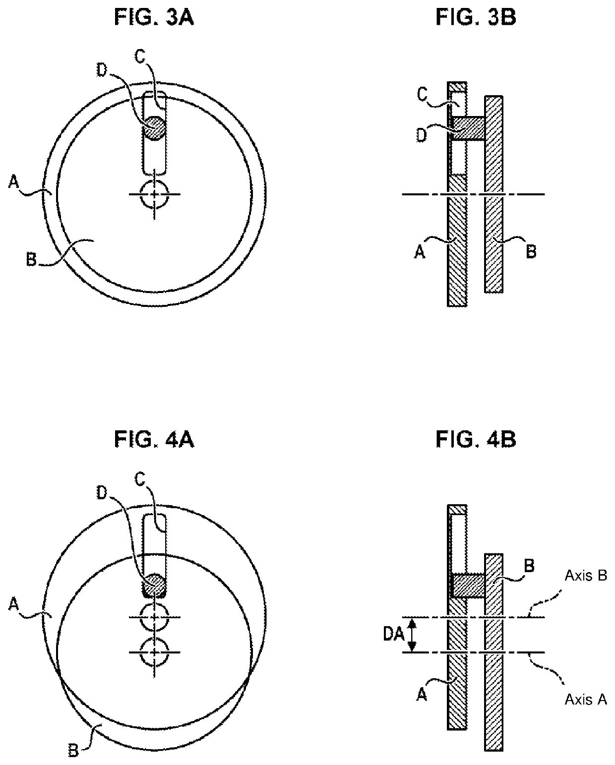
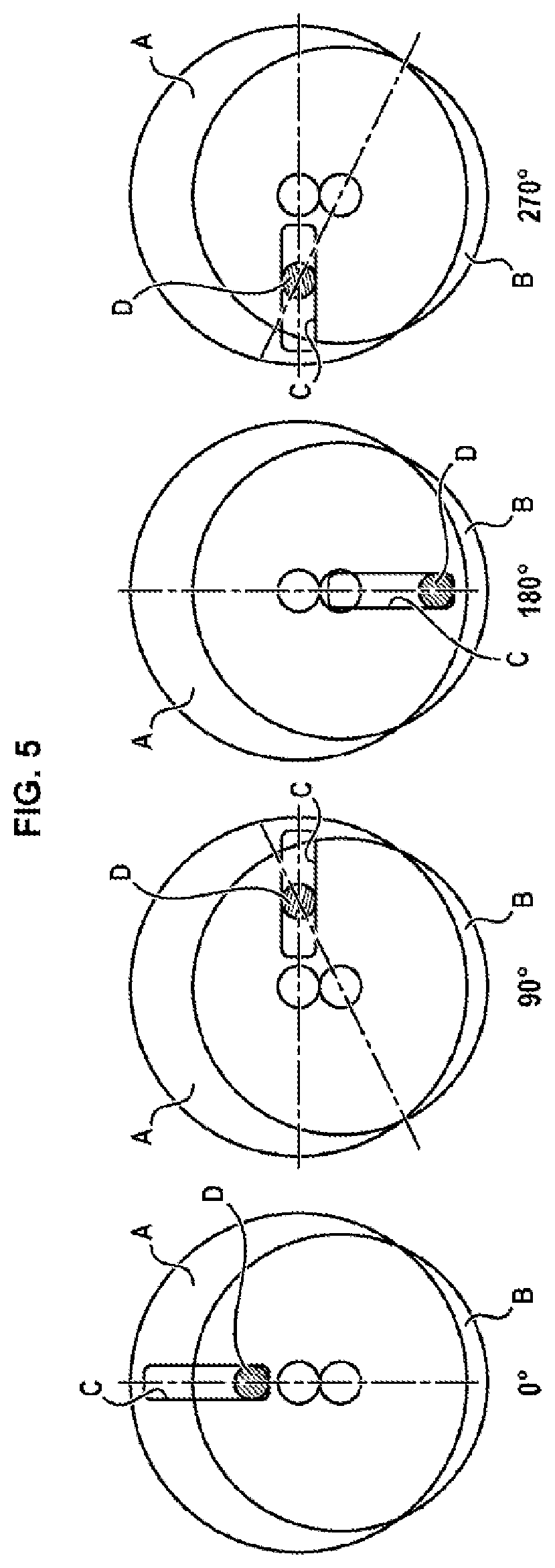
[0035]The basic elements implemented in the present invention are shown in FIG. 2: two elements A and B are driven one by the other while turning about two parallel axes. Element A is provided with a groove or slot C made in one of its radiuses. Element B is provided with a finger D, spaced apart by a distance x from the center of the disk. The finger D is provided to be able to slide in the groove or slot C of ...
PUM
 Abstract
Description
Claims
Application Information