An energy-saving compression refrigeration method

A compression refrigeration and compressor technology, which is applied in the direction of refrigerators, compressors, refrigeration components, etc., to achieve the effects of reducing the risk of liquid, reducing energy consumption, and low power consumption

Active Publication Date: 2017-02-22
EAST CHINA ENG SCI & TECH
View PDF7 Cites 0 Cited by
  • Summary
  • Abstract
  • Description
  • Claims
  • Application Information

AI Technical Summary

Problems solved by technology

[0003] The purpose of the present invention is to provide an energy-saving co

Method used


Image

  • An energy-saving compression refrigeration method

Examples


Example Embodiment

[0029] Specific embodiment:

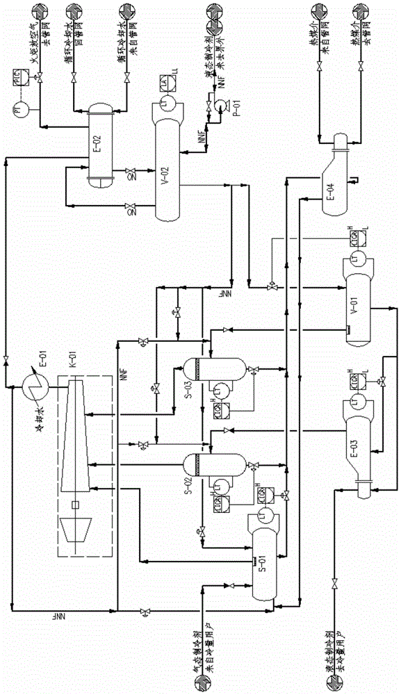
[0030] The core equipment of the refrigerant discharge evaporator system is a partitioned heat exchange evaporator. The liquid refrigerant separated from the inlet separator of each stage of the compressor is sent to the evaporator, heated by the heat medium, and then sent to the first stage of the compressor inlet.

[0031] The refrigerant is propylene. The gaseous propylene from the low-temperature methanol washing unit enters the first stage of the compressor after separating the entrained liquid propylene through a stage inlet separator. The compressed gaseous propylene is condensed into liquid propylene by circulating water through the outlet cooler and condenser, sent to the propylene buffer tank, and then enters the propylene flash tank after decompression. The gaseous propylene flashed in the propylene flash tank is separated from the entrained liquid propylene in the three-stage inlet separator, and then enters the third-stage inlet of the co...


PUM


Abstract

The invention discloses an energy-saving compression refrigeration method. The optimized design of the anti-surge circuit after the gaseous refrigerant is compressed and cooled in three stages ensures low power consumption of the compressor, and the refrigerant storage tank is incorporated into the compression refrigeration system to improve compression refrigeration. The stability of the circuit, the refrigerant evaporative emission system greatly improves the convenience of operation compared with the traditional power transmission method.

Description

technical field [0001] The invention relates to the technical field of compression refrigeration, in particular to an energy-saving compression refrigeration method. Background technique [0002] In the chemical industry, gaseous refrigerant pressurization, condensation and throttling refrigeration technology mostly provide the necessary cold environment for units such as low-temperature methanol washing, low-temperature oil washing, ammonia synthesis and liquid ammonia separation. In traditional industrial production, two-stage compression refrigeration is often used. The gaseous refrigerant flashed at the shell side of the subcooler is merged into the gaseous refrigerant flashed by the cooling user and then sent to the first stage inlet of the compressor; the anti-surge circuit of the compressor is derived from the compressor The outlet of the compressor; the condensed liquid refrigerant gravity flows to the pressure reducing valve to decompress and then flashes; the liqui...

Claims


Application Information

Patent Timeline
IPC IPC(8): F25B1/10F25B41/00F25B41/40
CPCF25B1/10F25B41/00F25J1/0087F25J1/0052F25J1/0298
Inventor 张文彪李全伟胡文生刘洪涛
Owner EAST CHINA ENG SCI & TECH
Why Eureka
Try Eureka