
Gas-liquid separator and heat exchange equipment

A gas-liquid separator and gas-liquid separation technology, applied in lighting and heating equipment, refrigeration and liquefaction, evaporator/condenser, etc., can solve unfavorable heat pump system installation and push, increase unit subcooling and superheating, Issues such as small size

Pending Publication Date: 2019-02-01
GREE ELECTRIC APPLIANCES INC
View PDF7 Cites 0 Cited by
  • Summary
  • Abstract
  • Description
  • Claims
  • Application Information

AI Technical Summary

Problems solved by technology

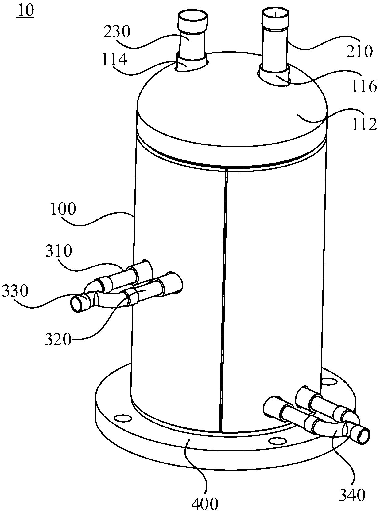
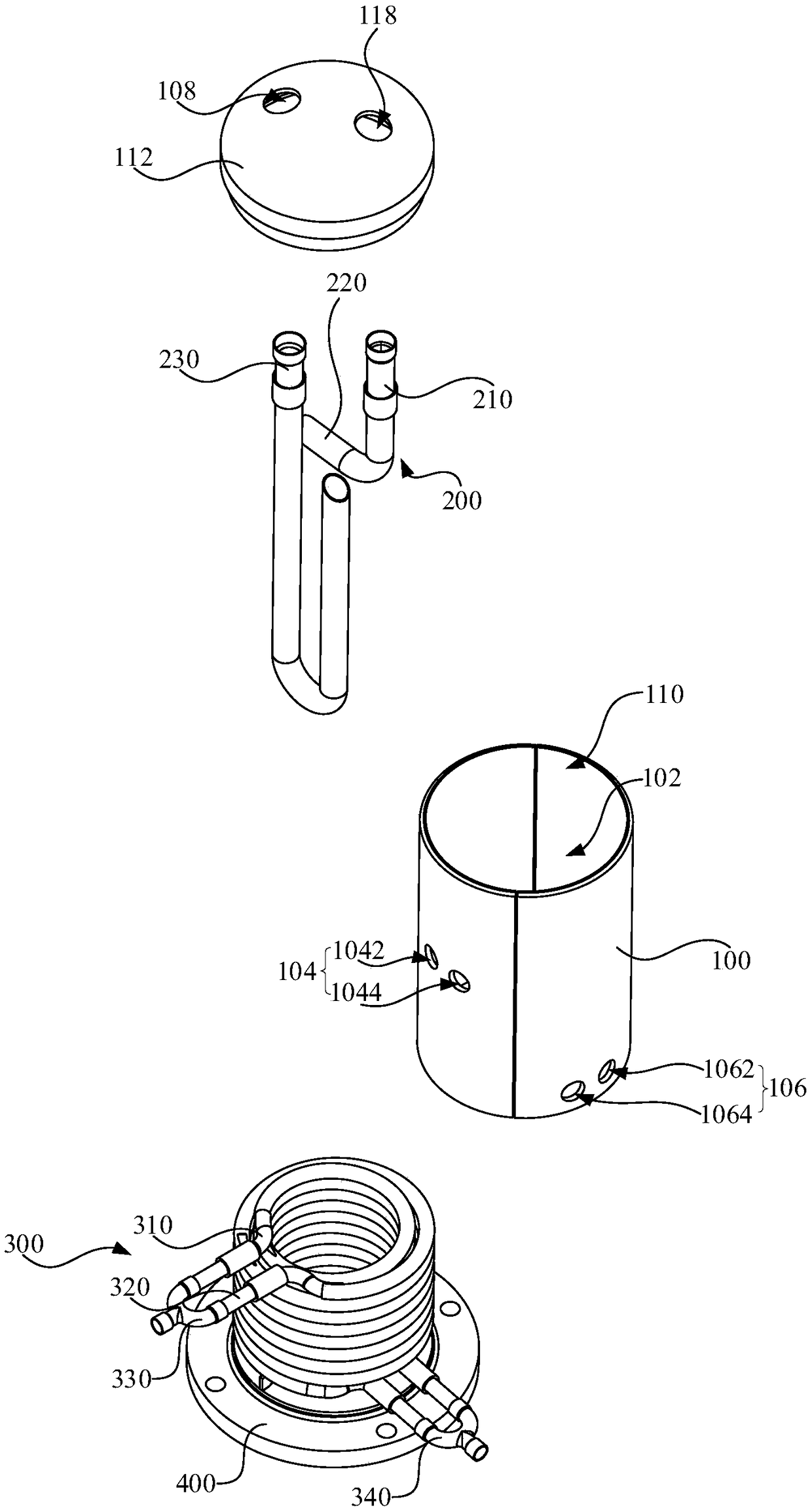
[0004] Based on this, after adding a heat exchanger to the traditional heat pump system, because the heat exchanger needs to occupy the unit cavity, which affects the installation of other components of the unit or the size of the unit is large, it is not conducive to the installation and promotion of the heat pump system. A gas-liquid separator and heat exchange equipment. The gas-liquid separator integrates a heat exchange structure and a gas-liquid separation structure, which saves the space of the unit and enables the gas-liquid separator to simultaneously store gaseous refrigerant and lubricating oil. The function of separating and increasing the degree of subcooling and superheating of the unit; the heat exchange equipment includes the above-mentioned gas-liquid separator, so the heat exchange equipment has the advantages of small size, high refrigeration efficiency and low risk of unit liquid entrainment

Method used


Image

  • Gas-liquid separator and heat exchange equipment
  • Gas-liquid separator and heat exchange equipment
  • Gas-liquid separator and heat exchange equipment

Examples


Embodiment Construction

[0025] In order to make the object, technical solution and advantages of the present invention clearer, the present invention will be further described in detail below in conjunction with the accompanying drawings and specific implementation methods. It should be understood that the specific embodiments described here are only used to explain the present invention, and do not limit the protection scope of the present invention.

[0026] It should be noted that when an element is referred to as being “disposed on” another element, it may be directly on the other element or there may also be an intervening element. When an element is referred to as being "fixed on" another element, it can be directly on the other element or intervening elements may also be present. When an element is referred to as being "connected to" another element, it can be directly connected to the other element or intervening elements may also be present. The terms "vertical," "horizontal," "left," "righ...


PUM


Abstract

The invention discloses a gas-liquid separator and heat exchange equipment. The gas-liquid separator comprises a shell, a gas-liquid separating structure and a heat exchange structure, wherein the shell comprises an accommodating cavity, a first through hole, a second through hole and a third through hole which are formed in a spaced manner are formed in the side wall of the accommodating cavity;the gas-liquid separating structure is used for separating a gaseous refrigerant and lubricating oil, the outlet of the gas-liquid separating structure communicates to the accommodating cavity, the air inlet of a compressor communicates to the accommodating cavity through the third through hole, and the inlet of the gas-liquid separating structure communicates to the outlet of a first heat exchanger; and the heat exchange structure is arranged in the accommodating cavity and comprises a heat exchange inlet and a heat exchange outlet, the heat exchange inlet communicates to the outlet of a second heat exchanger through the first through hole, and the heat exchange outlet communicates to the inlet of the first heat exchanger through the second through hole. The gas-liquid separator integrates the heat exchange structure and the gas-liquid separating structure, so that the space of a unit is saved.

Description

technical field [0001] The invention relates to the technical field of heat exchange equipment, in particular to a gas-liquid separator and heat exchange equipment. Background technique [0002] Under the national policy of energy conservation and emission reduction, in order to improve the competitiveness of products in the market, more and more manufacturers pay attention to the development of heat pump systems with large refrigeration capacity and high energy efficiency ratio. At present, in order to increase the capacity and energy efficiency ratio of the unit, the manufacturer needs to add a heat exchanger (also called an economizer) to the system to increase the subcooling degree and increase the temperature of the gas refrigerant. [0003] However, after adding a heat exchanger to a traditional heat pump system, the heat exchanger needs to occupy the cavity of the unit, which affects the installation of other components of the unit or the size of the unit is large, wh...

Claims


Application Information

Patent Timeline
IPC IPC(8): F25B43/00F25B39/00
CPCF25B39/00F25B43/00F25B2400/23F25B2339/044
Inventor 罗伟新王传华温德平魏星
Owner GREE ELECTRIC APPLIANCES INC
Learn More