Detector of objects by microwave frequency echo analysis

a technology of microwave frequency and echo analysis, applied in the field of detection devices, can solve the problems of real danger to human beings when exposed to regular use, difficult to implement, and inability to use x-rays for non-medical purposes, and achieve the effect of simple production and great simplicity

Inactive Publication Date: 2007-01-04
THALES SA
View PDF7 Cites 0 Cited by
  • Summary
  • Abstract
  • Description
  • Claims
  • Application Information

AI Technical Summary

Benefits of technology

[0009] The proposed device largely resolves these drawbacks. In practice, it can be used to perform a simultaneous measurement at several points from a single transmitter and detector pairing. Thus, a large check area can be covered without taking an image while fairly accurately locating a suspect object, so facilitating the intervention of a security agent for a more thorough investigation. Furthermore, the millimetric waves used by this device do not present any hazards to human health and therefore can be used widely. Analyzing signals does not require significant computation power and conventional computer resources are sufficient for this purpose. In the end, this device offers great simplicity and can be produced inexpensively.

Problems solved by technology

However, the use of X-rays for a non-medical purpose is prohibited in a large number of countries and in particular in most European states.
In practice, this technique includes a real danger for the human being when exposed to regular use.
They are complex to implement.
Some use costly mirror-deflection systems.
Also, the techniques consisting in taking the image of the human body come up against an ethical problem.
Now, the passenger will not accept being analyzed nude by an operator.
One of the main drawbacks of these single-detector systems is that the measurement is a spot or almost spot measurement.
Consequently, checking a subject can take some time.
These devices are ill-suited to quickly checking a large number of passengers.
It can also be difficult to determine very accurately the position or the size of a suspect object.

Method used


Image

  • Detector of objects by microwave frequency echo analysis
  • Detector of objects by microwave frequency echo analysis
  • Detector of objects by microwave frequency echo analysis

Examples


Embodiment Construction

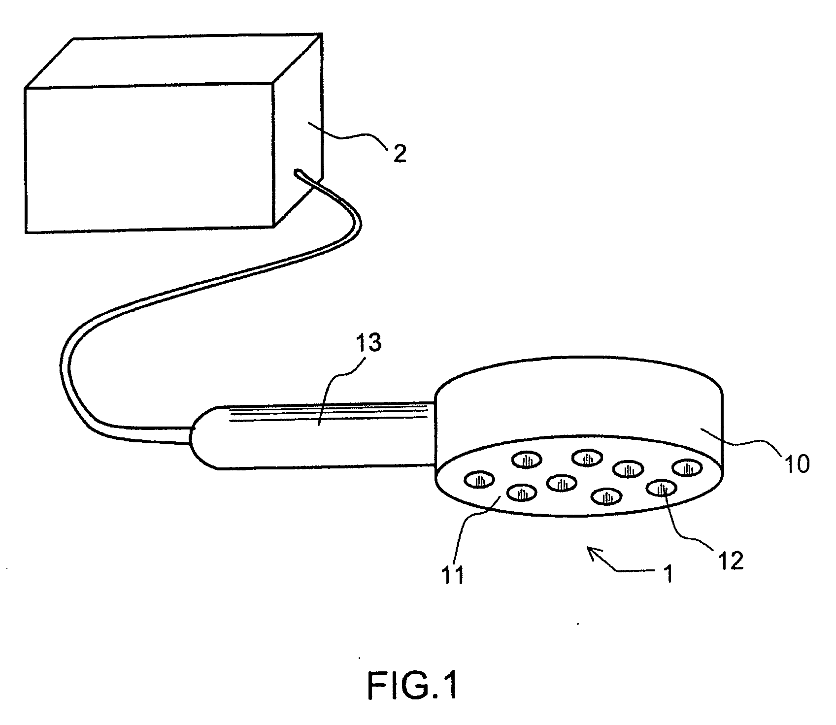
[0049]FIG. 1 represents a view of the detection system according to the invention. It essentially comprises two main elements: [0050] a detector 1 comprising a system for transmitting and receiving microwave frequency signals; [0051] an electronic data processing system 2 linked to said structure.

[0052] Externally, the structure of the detector 1 essentially comprises: [0053] an enclosure 10 with a measurement surface 11 designed to be positioned in the vicinity of the human body, said surface 11 having a certain number of holes 12; [0054] a handle 13 or any other handling means for manipulating the structure.

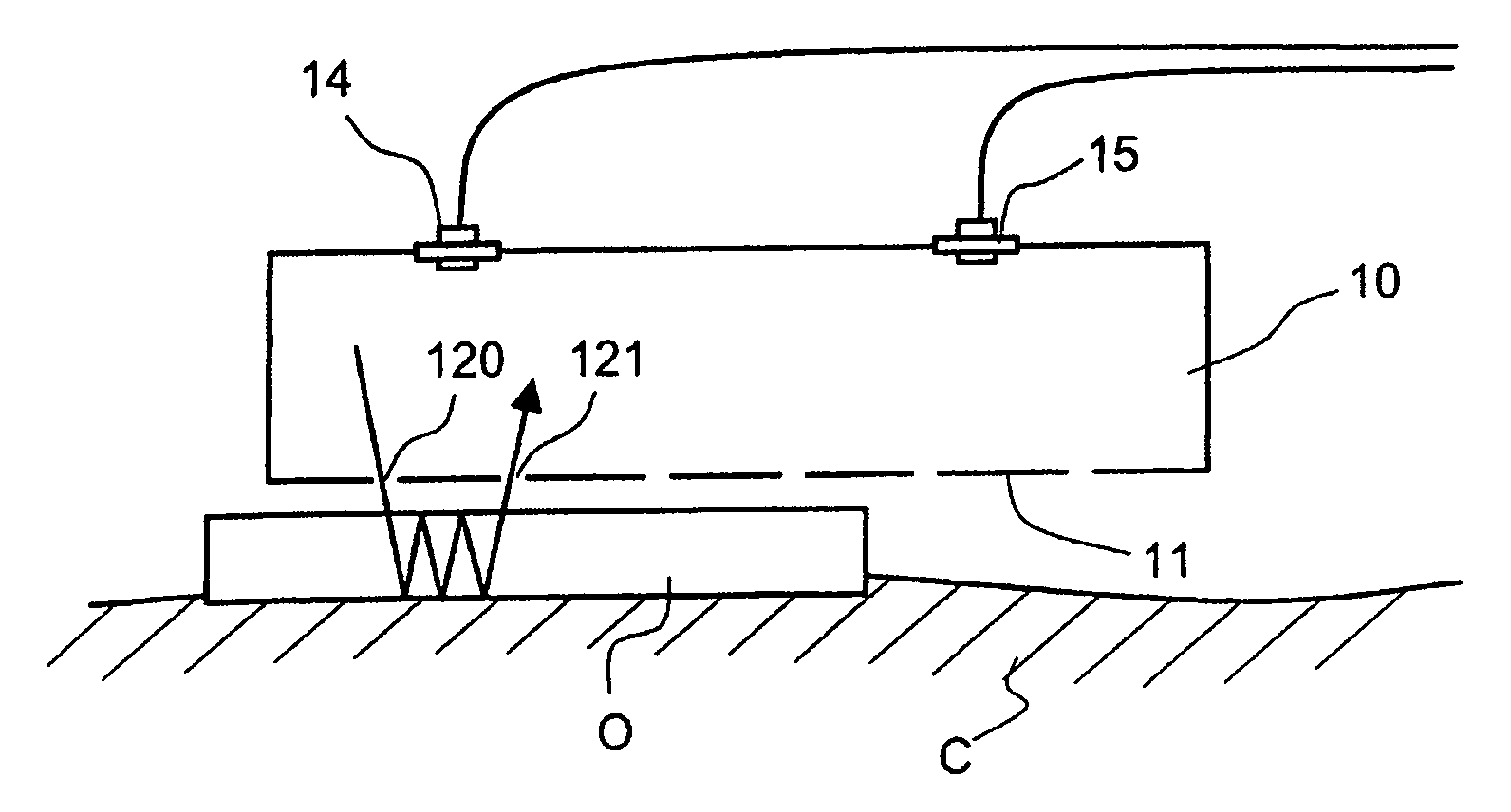
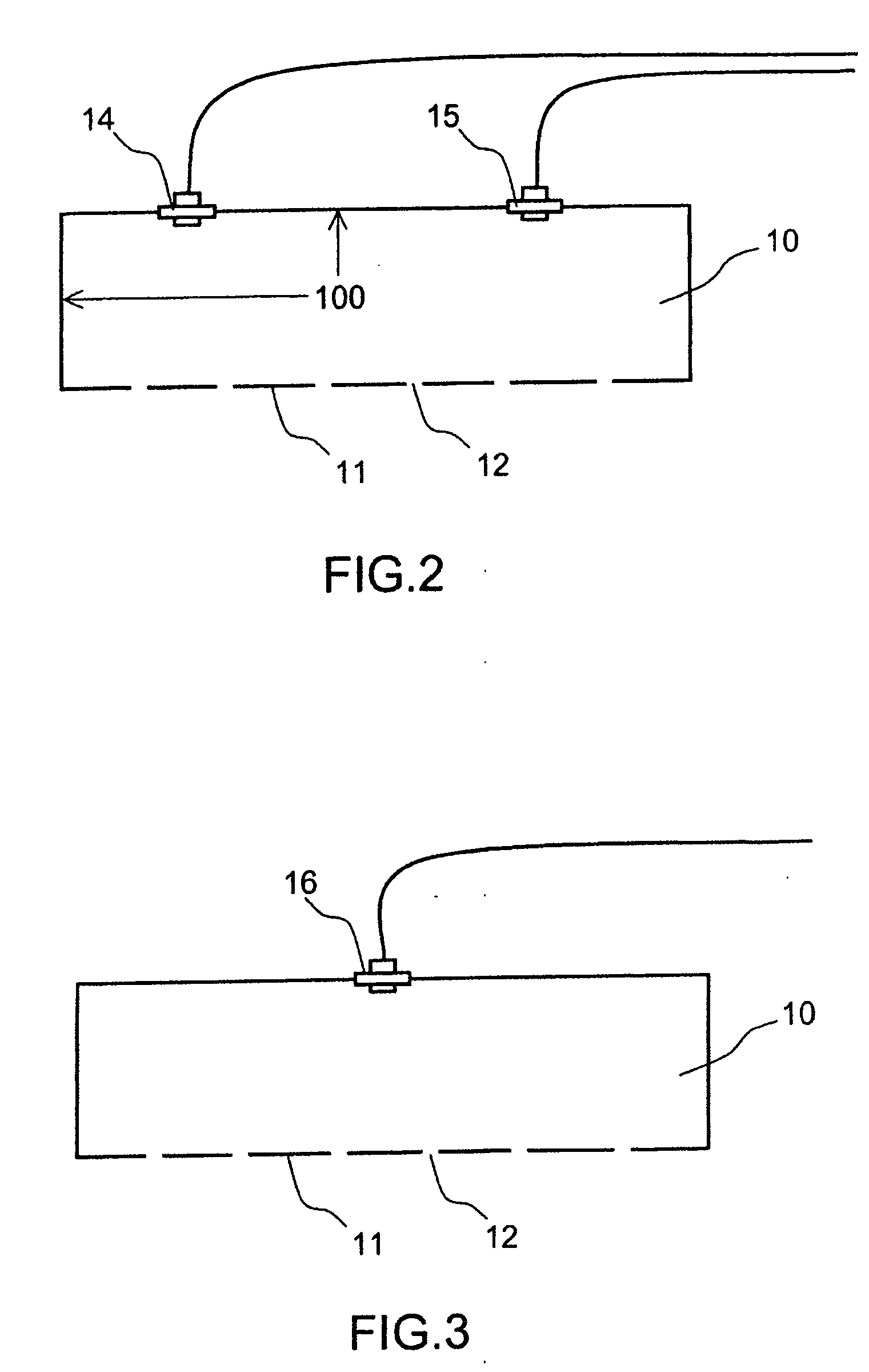
[0055]FIG. 2 represents a first cross-section view of the enclosure 10. This enclosure mainly comprises walls 100 reflecting the millimetric waves, a measurement surface 11 with holes 12. A microwave frequency transmitter 14 and a receiver 15 are disposed inside the enclosure. As indicated in FIG. 3, the transmitter and the receiver can be combined in a single transceiver dev...


PUM


Abstract

The field of the invention is that of devices for detecting non-metallic objects concealed on human subjects. These devices are more particularly dedicated to the surveillance and protection of reserved access areas, such as airport areas. The device according to the invention comprises a portable detector comprising a transmitter and a receiver of microwave frequency signals disposed in an enclosure of chaotic geometry including a plurality of measurement holes. The microwave frequency signal measured by this detector depends on the nature of the objects disposed under the holes. A processing device linked to this detector is used to correlate the measured signals with prerecorded signals. When the correlation exceeds a certain threshold corresponding to the presence of suspect objects, an alarm is generated.

Description

BACKGROUND OF THE INVENTION [0001] 1. Field of the Invention [0002] The field of the invention is that of devices for detecting objects concealed on human subjects. These devices are more particularly dedicated to the surveillance and protection of airport areas and transport airplanes, but can also be positioned at the entrance of protected buildings or controlled access areas such as boat or train embarkation platforms. [0003] 2. Description of the Prior Art [0004] To ensure the safety of the passengers in aircraft, cargo hold luggage and hand baggage is checked by X-ray imaging systems. The passengers themselves pass only through a metal-detector gate. Now, it is essential to detect on a passenger non-metallic objects that present a real danger such as explosives or ceramic weapons. [0005] To overcome this security omission, some airports have put in place, experimentally, X-ray scanners for the passengers themselves. However, the use of X-rays for a non-medical purpose is prohib...

Claims


Application Information

Patent Timeline
Patent Type & Authority Applications(United States)
IPC IPC(8): G01R27/04
CPCG01N22/00G01V8/005G01S13/04
Inventor MILLET, NICOLASLEHUREAU, JEAN-CLAUDE
Owner THALES SA
Why Eureka
Try Eureka