Fast snap-on connector with latches with symmetrical jaws

Inactive Publication Date: 2014-12-04
NOBEL PLASTIQUES
View PDF4 Cites 7 Cited by
  • Summary
  • Abstract
  • Description
  • Claims
  • Application Information

AI Technical Summary

Benefits of technology

The invention is about improving a connector by making it stronger and more durable. The connection is achieved through a structure that increases the resistance of the jaws to pulling out. The lock parts are designed to be very robust, and the jaws are designed to be strong. The connector also has a surrounding bearing member that acts as a fixed part or a part of the antagonistic mobile latch part, which increases the elastic reaction force. Overall, the invention makes the connector more durable and user-friendly.

Problems solved by technology

The lozenge-shaped single latch part proves in use in to be relatively fragile.
To allow its elastic functioning, it is necessary to provide connecting parts that are neither too thick nor too rigid but because of this the jaws may be insufficiently retained and not exert on the flange of an end fitting a sufficient force to prevent the end fitting from being pulled out.

Method used


Image

  • Fast snap-on connector with latches with symmetrical jaws
  • Fast snap-on connector with latches with symmetrical jaws
  • Fast snap-on connector with latches with symmetrical jaws

Examples


Embodiment Construction

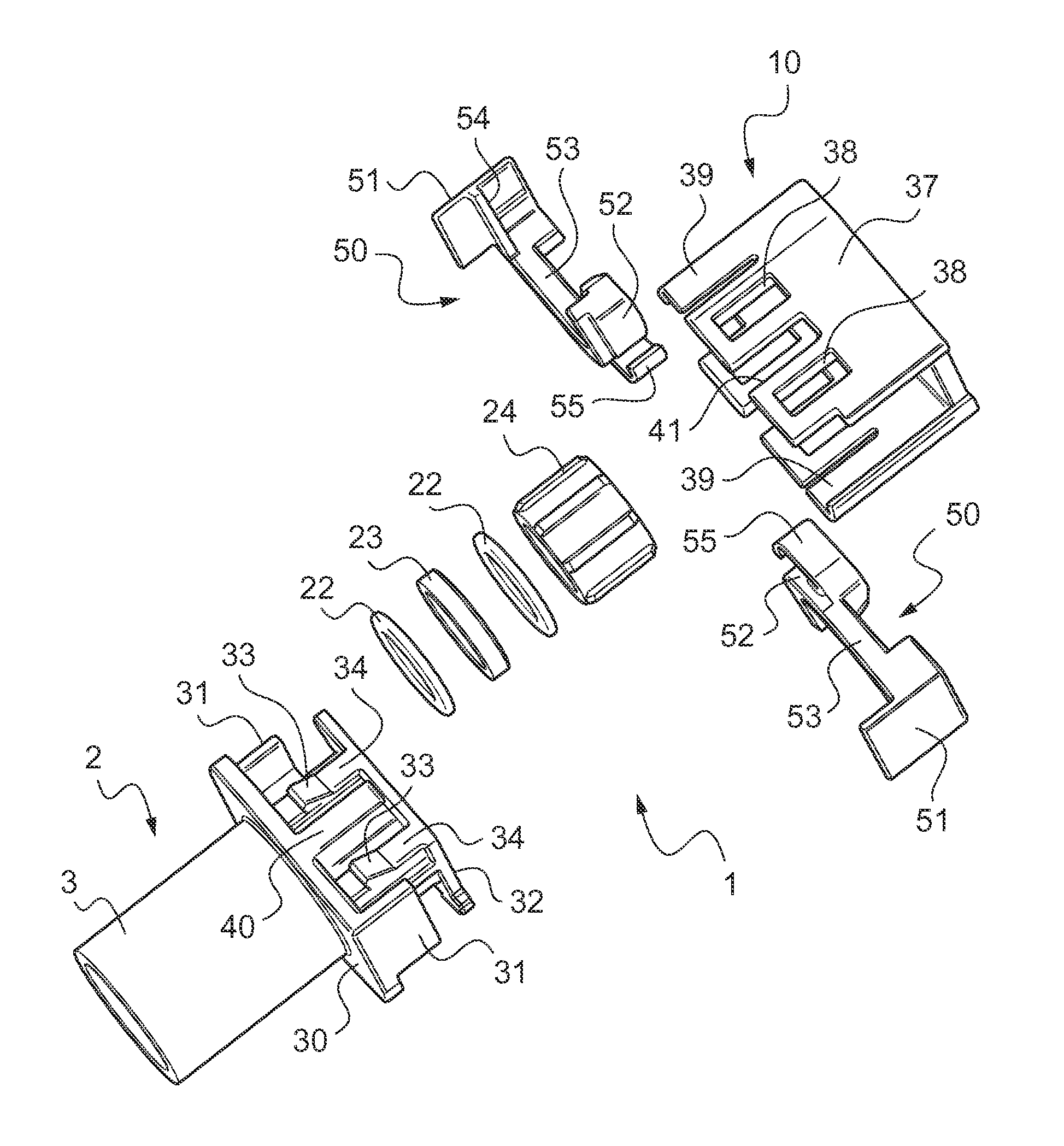
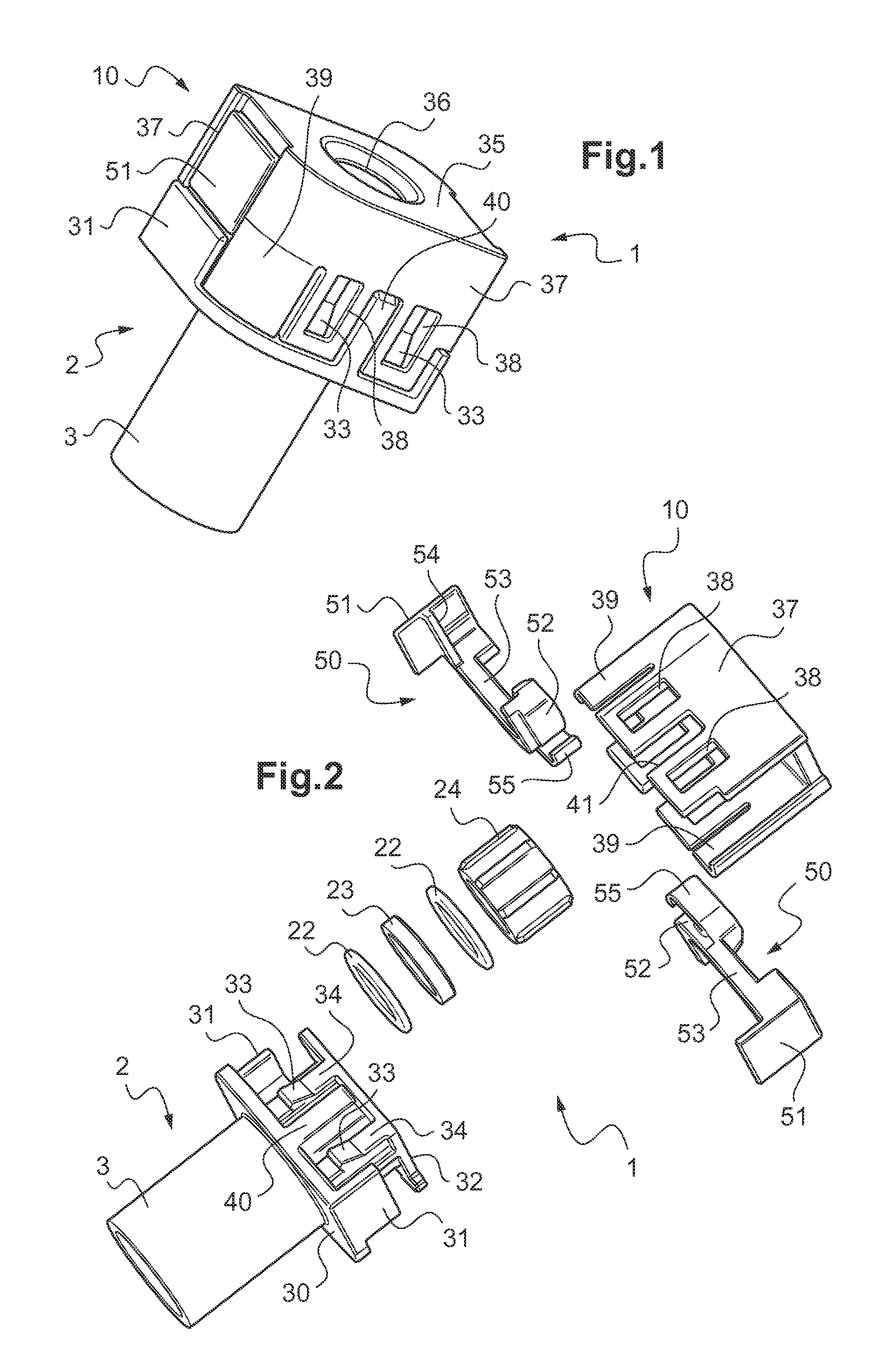
[0025]The fast connector 1 essentially includes a body 2 that includes at the rear a tubular portion in the form of a hollow spigot 3 and at the front a cylindrical cavity or chamber 4 in which must be engaged a male end fitting 20 formed of a bush 26 provided with a clip-on flange 25. The spigot 3 may have on its exterior surface connection profiles, not shown, for example pine tree profiles or single or double bulges, for forcible engagement in a pipe, or may be welded (by rotation, ultrasound, induction or laser welding) to a tube or some other member. A cap 10 is clipped onto the front of the body 2 to form a transverse latch housing to be described in detail later.

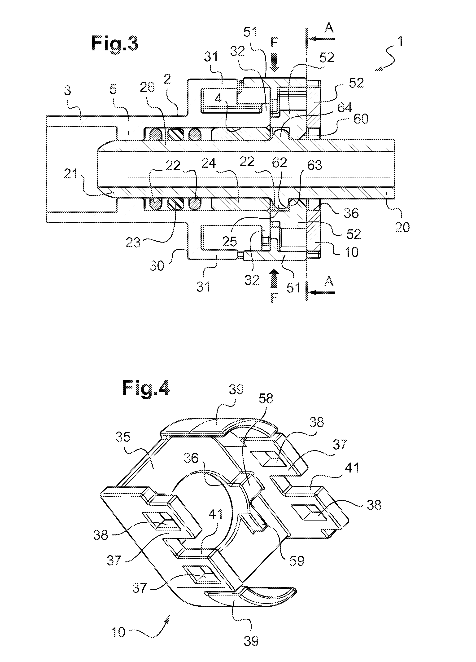
[0026]As FIG. 3 shows, the cylindrical chamber 4 is separated from the interior cylindrical volume of the spigot 3 by a toroidal rib 5 defining a cylindrical passage having an inside diameter adapted to have the distal end 21 of the male end fitting 20 pass through it. The cylindrical chamber 4 is able to receive two ...


PUM


Abstract

A female snap-on connector (1) intended to cooperate with a male attachment end fitting (20) of the type with a central bush (26) and a flange (25) includes a body (2) forming a cylindrical cavity and to which is fixed a cap (10) forming a housing for two symmetrical latch parts (50) disposed head-to-spigot, mounted to slide in the same transverse direction, each latch part (50) including a manoeuvring part (51), a rigid connecting rod (53) and a jaw (52) as well as spring means (55) for continuously urging each latch part (50) elastically into its rest position in which the jaw (52) is moved toward the axis and the manoeuvring part (51) is in its radially outermost position.

Description

TECHNICAL FIELD OF THE INVENTION[0001]The present invention concerns a female snap-on connector intended to cooperate with a flanged male attachment end fitting.BACKGROUND OF THE INVENTION[0002]In the present document, this combination of male and female members will be referred to as a “connector”. It is standard practice, notably in the automotive industry, to use such snap-on connectors for the fast and demountable connection of a fluid (for example fuel, oil or water) circuit element to another circuit element. The industry has substantially standardized on male end fittings including a cylindrical barrel surrounded by a flange and the female connectors include a cylindrical cavity intended to receive at least the end of the bush and an elastic latch intended to lock the rear of the flange once the latter is in place. O-rings provide the seal around the male end fitting.[0003]The document EP 0 605 801 A discloses a connector in which the latch is symmetrical and disposed transve...

Claims


Application Information

Patent Timeline
IPC IPC(8): F16L21/08
CPCF16L21/08F16L37/0841F16L37/086F16L37/0985F16L37/1225
Inventor MILHAS, PIERREPAQUIS, YVONPIETTE, GAEL
Owner NOBEL PLASTIQUES
Why Eureka
Try Eureka