
Electronic stamper

Inactive Publication Date: 2012-05-17
GRIFITI
View PDF0 Cites 1 Cited by
  • Summary
  • Abstract
  • Description
  • Claims
  • Application Information

AI Technical Summary

Benefits of technology

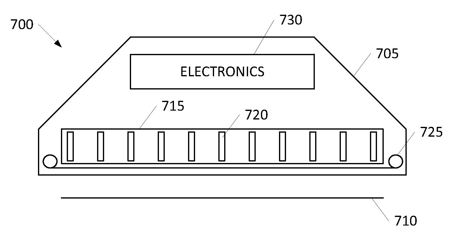
[0009]Disclosed is a versatile and convenient electronic stamper that overcomes limitations of conventional systems including greater robustness in message transfer as well as disproportionate costs. A print solution includes a hand-held housing defining a print area aperture; and a printhead array including a plurality of rows and a plurality of columns of print elements, the printhead sized to substantially cover the print area aperture and configured to apply a print element to any part of the print area aperture without relative motion between the print head and the print area aperture.

Problems solved by technology

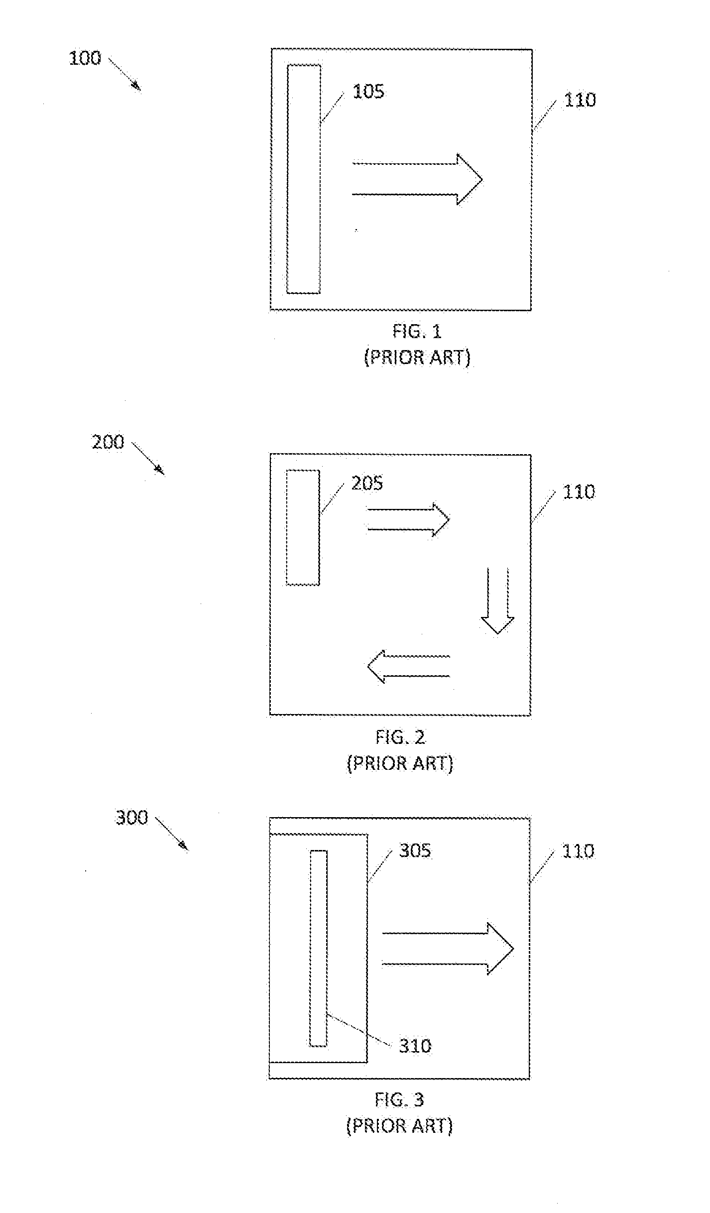
The slower the conventional print solution moves the printhead, the longer a user is required to maintain the stamper location fixed.
Movement before completion risks distortion and the longer it takes, the more a user is dissatisfied with the “stamping” function.

Method used


Image

  • Electronic stamper
  • Electronic stamper
  • Electronic stamper

Examples


Embodiment Construction

[0020]Embodiments of the present invention provide apparatus and method for a versatile and convenient electronic stamper that overcomes limitations of conventional systems including greater robustness in message transfer as well as disproportionate costs. The following description is presented to enable one of ordinary skill in the art to make and use the invention and is provided in the context of a patent application and its requirements.

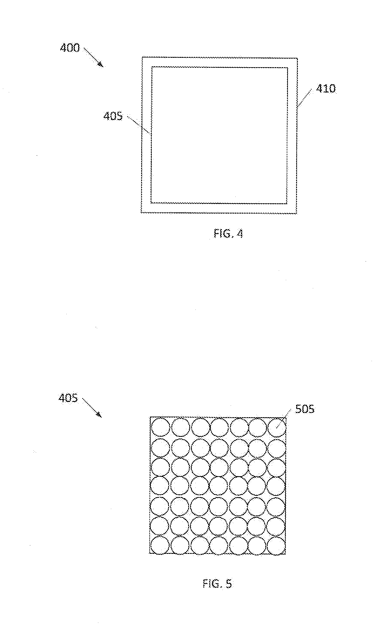
[0021]FIG. 4 is a print solution embodiment 400 of the present invention including a fixed printhead 405 printing to a print area 410 without relative motion between printhead 405 and print area 410. FIG. 5 is a detailed representation of an embodiment of printhead 405 shown in FIG. 4. Printhead 405 includes an array (shown as a regular matrix of M×N print elements 505). In a preferred embodiment, print elements 505 are inkjets, though other implementations may use a different imaging technology. In the preferred embodiments, the desired technolo...


PUM


Abstract

A versatile and convenient electronic stamper that overcomes limitations of conventional systems including greater robustness in message transfer as well as disproportionate costs. A print solution includes a hand-held housing defining a print area aperture; and a printhead array including a plurality of rows and a plurality of columns of print elements, the printhead sized to substantially cover the print area aperture and configured to apply a print element to any part of the print area aperture without relative motion between the print head and the print area aperture.

Description

BACKGROUND OF THE INVENTION[0001]The present invention generally relates to office “stamper” replacement, and more particularly to electronic indicia application systems and methods for replacing stamper products.[0002]As used herein, “stamper” refers to the ubiquitous “stamp” type product used in businesses and homes all over the world. This class of product includes rubber stamps, business stamps, ink stamps, “print” kits, and the like, whether they are self-inking or use an inking stamp pad or replaceable cartridge. For mechanical stampers, there are products that are single function (i.e., they apply a single “message” to a receiving article when “stamped” and there are products that are multifunction and may be configured to apply a message selected from a set of messages.[0003]These products and methods are ubiquitous because of their simplicity, effectiveness, and cost. There are well-known drawbacks to these systems including uniform and consistent application of ink to the ...

Claims


Application Information

Patent Timeline
IPC IPC(8): B41J3/36
CPCB41J3/36
Inventor WESSELLS, PHILIP G.WOODS, MICHAEL E.
Owner GRIFITI
Learn More