Sensor component

a technology of sensor components and components, applied in the direction of measuring apparatuses for damping movement parts, acceleration measurement using interia forces, instruments, etc., can solve the problems of affecting the damping properties of the sensor component negatively, mechanical contact requires a costly assembly, and a certain minimum size of the sensor component, so as to achieve advantageously affordable and improve the damping effect, the effect of preventing the excitation of additional interference modes

Active Publication Date: 2010-09-30
ROBERT BOSCH GMBH
View PDF25 Cites 30 Cited by
  • Summary
  • Abstract
  • Description
  • Claims
  • Application Information

AI Technical Summary

Benefits of technology

[0010]In one refinement of the sensor component, an additional mass may be situated on the substrate. This has the advantage that the resonant frequency of the system formed from the substrate and the elastomer element is reduced, whereby the damping is improved.
[0011]In another refinement of the sensor component, the substrate is pressed against the elastomer element by at least one holding-down element. In addition, the holding-down element is able to produce an electrical connection between a ground contact of the substrate and a ground contact of the housing. This specific embodiment advantageously permits a symmetrization of the clamping of the substrate, whereby the excitation of additional interference modes is prevented. In addition, an advantageous EMC screening of the sensor component is achieved.
[0012]According to one specific embodiment, the elastomer element has a plurality of conductive and insulating layers. Such elastomer elements are advantageously obtainable inexpensively. In another specific embodiment, the elastomer element has a silicone and conductive particles or filaments integrated into the silicone. This permits better contacting and makes possible lower contact resistances. According to one additional alternative specific embodiment, the elastomer element is produced from conductive, extrudable silicone. This advantageously enables an especially simple production of the sensor component.

Problems solved by technology

The different connecting techniques for the electrical and mechanical contacting require a costly assembly and a certain minimum size of the sensor component.
In addition, the separately executed electrical contacting is able to influence the damping properties of the sensor component negatively.

Method used


Image

  • Sensor component
  • Sensor component
  • Sensor component

Examples


Embodiment Construction

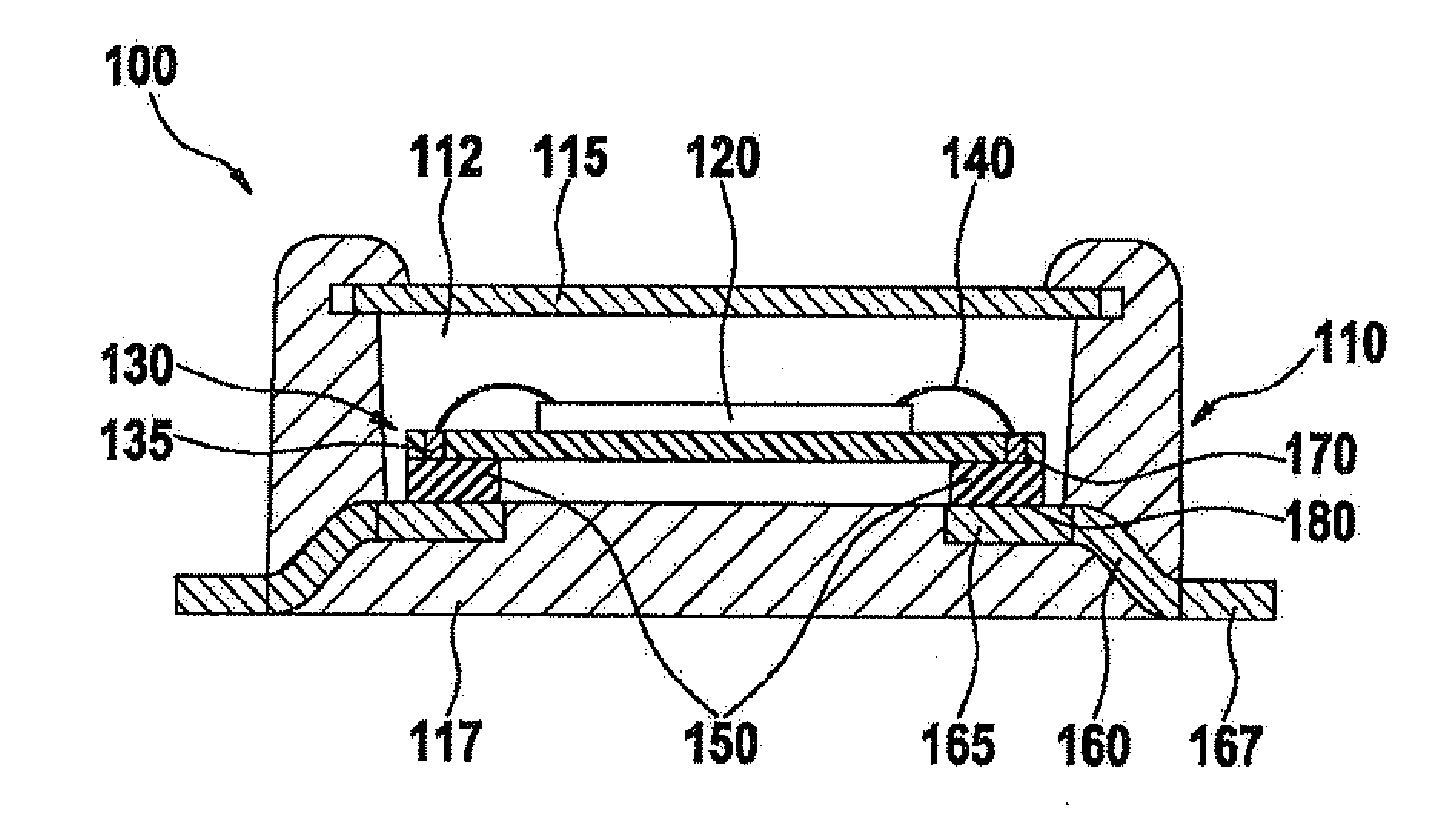
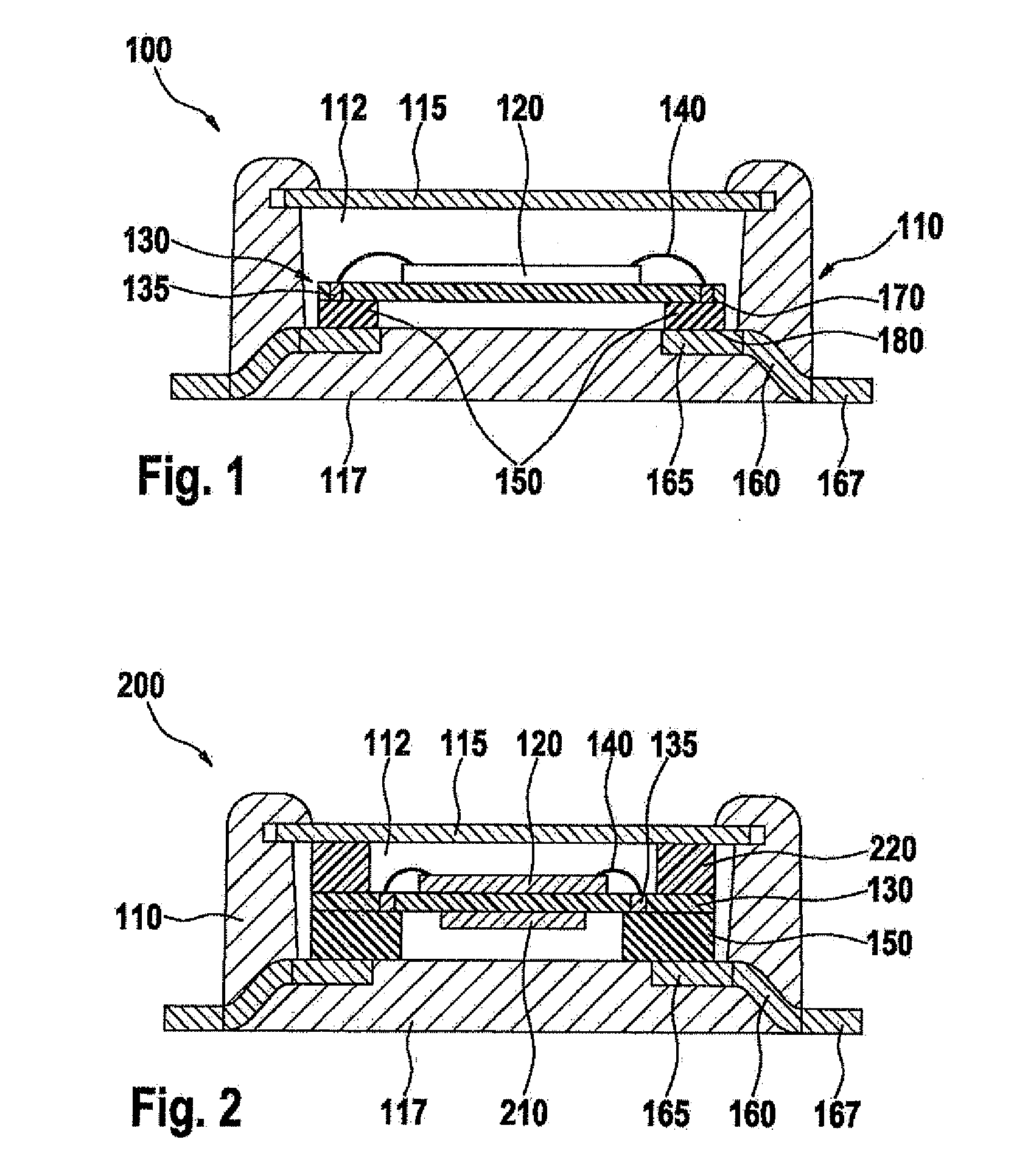
[0019]FIG. 1 shows a schematic representation of a section through a sensor component 100, according to a first specific embodiment. Sensor component 100 includes a housing 110 which encloses a sensor chamber 112 between a cover 115 and a floor 117 of the housing 110. Housing 110 may be a premold housing, for example.

[0020]A sensor chip 120 is situated in sensor chamber 112 within housing 110. Sensor chip 120 may have a micromechanical sensor, for instance, an acceleration sensor or a rotation-rate sensor. Sensor chip 120 may also have another type of sensor. On sensor chip 120, evaluation electronics, for instance in the form of ASICs, may already be provided.

[0021]Sensor chip 120 is situated on a substrate 130. Substrate 130 may be a printed circuit board, for example. In the exemplary embodiment of FIG. 1, sensor chip 120 is situated on substrate 130 in such a way that the active sensor components of sensor chip 120 are provided on the side of sensor chip 120 facing away from sub...


PUM


Abstract

A sensor component having a housing and a sensor chip situated in it. The sensor chip is connected mechanically to the housing via at least one elastomer element. In addition, the sensor chip is also connected electrically to the housing via the at least one elastomer element.

Description

CROSS-REFERENCE[0001]The present application claims the benefit under 35 U.S.C. §119 of German Patent Application No. 102009001930.8 filed Mar. 27, 2009, which is expressly incorporated herein by reference in its entirety.FIELD OF THE INVENTION[0002]The present invention relates to a sensor component.BACKGROUND INFORMATION[0003]Conventionally, a sensor, such as an acceleration sensor or a rotation-rate sensor, may be placed into a housing having integrated mechanical damping elements for mechanically decoupling outside influences, such as vibrations at the working frequency of the sensor. Such a model is described in German Patent Application No. DE 10 2006 026 878 A1, for instance. A spring-mass system is used for the vibration damping of the sensor, in this context. The spring-mass system is made up of a floor plate, which is connected to a frame of the housing via an elastomer element as the spring element, having self-damping for the dissipation of the vibrational energy.[0004]I...

Claims


Application Information

Patent Timeline
Patent Type & Authority Applications(United States)
IPC IPC(8): G01P15/02G01C19/5783
CPCB81B7/0058B81B2201/0235B81B2201/0242G01P1/023G01D11/10G01D11/245G01C19/5783H01L2224/48091H01L2924/00014
Inventor OFFTERDINGER, KLAUS
Owner ROBERT BOSCH GMBH
Why Eureka
Try Eureka