Surface acoustic wave device and communications apparatus using the same

a surface acoustic wave and waveguide technology, applied in piezoelectric/electrostrictive/magnetostrictive devices, piezoelectric/electrostriction/magnetostriction machines, electrical equipment, etc., can solve the problems of increasing equipment cost, time and labor costs, and difficulty in controlling resonance frequency on a wafer basis, so as to reduce the fluctuation of resonance frequency and reduce the time for controlling frequency. , the effect of reducing the fluctuation

Inactive Publication Date: 2005-02-15
SEIKO EPSON CORP
View PDF9 Cites 31 Cited by
  • Summary
  • Abstract
  • Description
  • Claims
  • Application Information

AI Technical Summary

Benefits of technology

Also, another object of the present invention is to facilitate regulating the frequency of the surface acoustic wave device.
In the present invention with such an arrangement, the fluctuation in resonance frequency can remarkably be reduced with respect to the variations in the electrode width of the IDT electrode. Therefore, there is no need for an expensive and high-precision aligner and so on to reduce the fluctuation in resonance frequency due to the formation error of the electrode width. Also, not only photolithography processing and etching processing, but also the frequency of the formed SAW resonator can easily be controlled. Thus, the time for controlling the frequency can be decreased and the cost can be reduced.

Problems solved by technology

Therefore, it is difficult to control the resonance frequency on a wafer basis.
Therefore, the frequencies of the surface acoustic wave devices must be controlled individually when it is mounted in a package or the like, which can be both time and labor intensive in order to control the resonance frequency.
Thus, the cost of equipment is increased, resulting in an increase in the cost of the surface acoustic wave device.

Method used


Image

  • Surface acoustic wave device and communications apparatus using the same
  • Surface acoustic wave device and communications apparatus using the same
  • Surface acoustic wave device and communications apparatus using the same

Examples


Embodiment Construction

A preferable embodiment of a surface acoustic wave device and a communications apparatus using the same, according to the present invention, will be specifically described with reference to the attached drawings. Components corresponding to the components described in the conventional art will be denoted by the same numerals and a description thereof will be omitted.

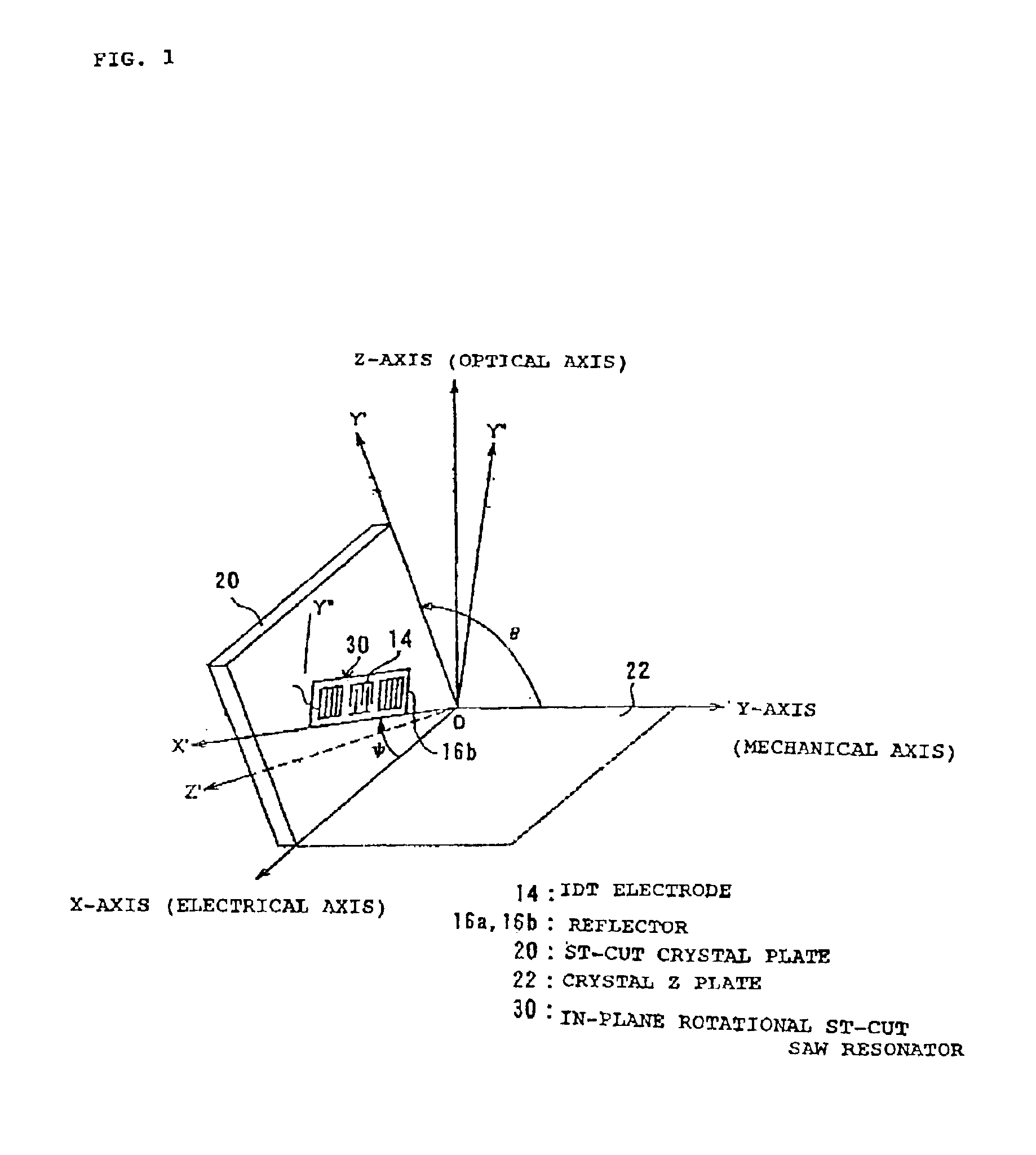
FIG. 1 is an exemplary diagram explaining the cut angles of crystal for obtaining a surface acoustic wave resonator (SAW resonator) according to the present invention. In FIG. 1, the X-axis, Y-axis, and Z-axis represent the respective crystallographic axes of the crystal, wherein the X-axis is a so called electrical axis, the Y-axis is a mechanical axis, and the Z-axis is an optical axis.

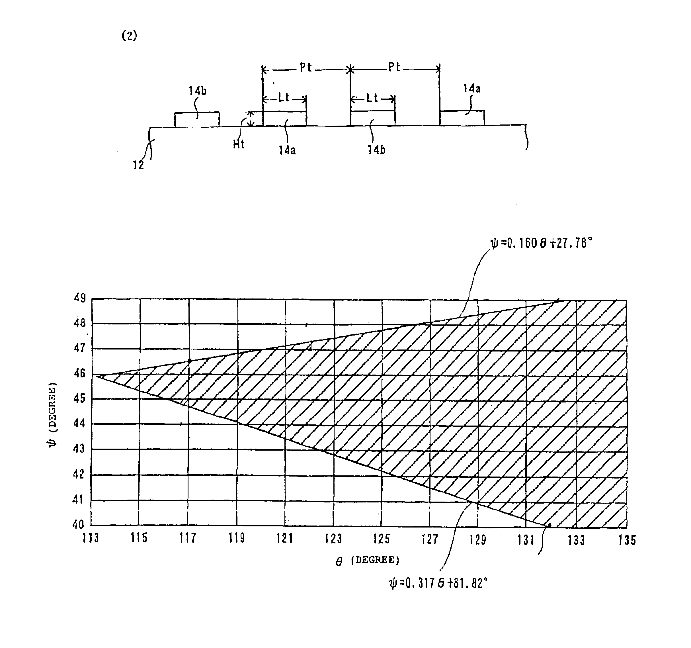
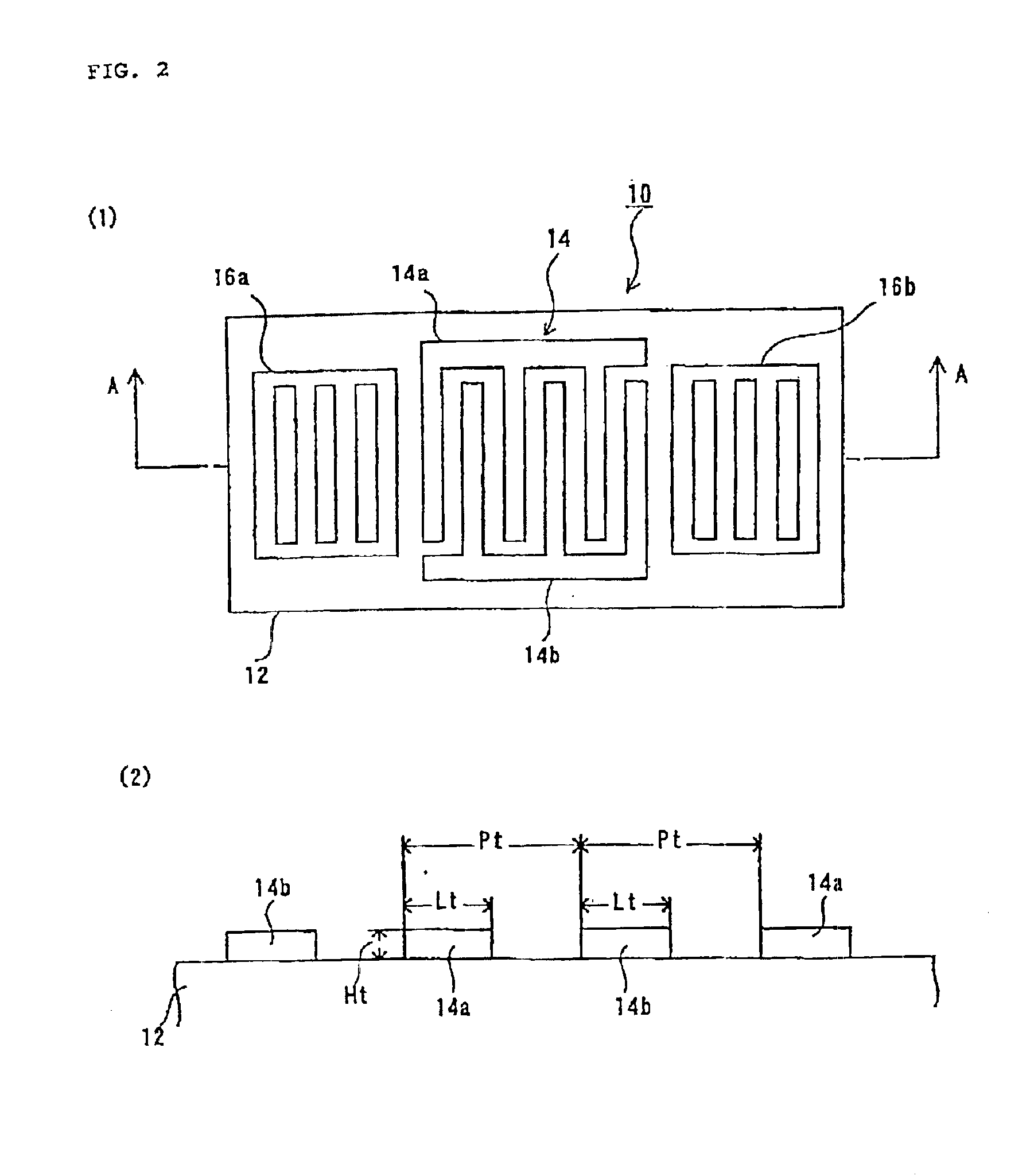
An ST-cut crystal plate 20 for forming an ST-cut SAW resonator is obtained by rotating a crystal Z plate 22 having Eulerian angles of (0°, 0°, and 0°) around the X-axis by θ=113° to 135° and cutting it out along the crystallographic axes...


PUM


Abstract

The invention provides an in-plane rotational ST-cut SAW resonator that is formed of an in-plane rotational ST-cut crystal plate having Eulerian angles of (0°, 113° to 135°, and ±(40° to 49°)). The in-plane rotational ST-cut SAW resonator can include an interdigital transducer (IDT) electrode for exciting a Rayleigh wave on the main surface. The ratio Lt / Pt of the electrode width Lt and the interelectrode pitch Pt of the IDT electrode is 0.5 or more and 0.65 or less. Accordingly, a reduction in the fluctuation in resonance frequency relative to the variations in an IDT electrode of a surface acoustic wave device by using the in-plane rotated ST-cut crystal plate around the Z′-axis can be achieved.

Description

BACKGROUND OF THE INVENTION1. Field of InventionThe present invention relates to a surface acoustic wave device using crystal glass. More specifically, the invention relates to a surface acoustic wave device using a so-calledin-plane rotational ST-cut crystal plate, and a communications apparatus using the same.2. Description of Related ArtSurface acoustic wave devices represented by surface acoustic wave resonators and surface acoustic wave filters utilizing a surface acoustic wave (SAW) use a planar piezoelectric material. Known surface acoustic wave devices have an IDT (Interdigital Transducer) electrode on the main surface of a piezoelectric flat plate and has reflectors on both sides of the IDT electrode to oscillate a high frequency region stably. ST-cut surface acoustic wave devices are known in which an ST-cut crystal plate is used as a piezoelectric material that forms a surface acoustic wave device for the purpose of reducing the fluctuation in frequency relative to temper...

Claims


Application Information

Patent Timeline
Patent Type & Authority Patents(United States)
IPC IPC(8): H03H9/25H03H9/00H03H9/02
CPCH03H9/25H03H9/02543
Inventor YAMAZAKI, TAKASHIIIZAWA, KEIGOKANNA, SHIGEO
Owner SEIKO EPSON CORP
Why Eureka
Try Eureka