A mobile terminal heat dissipation structure and mobile terminal
A mobile terminal and heat dissipation structure technology, which is applied in the field of communication, can solve the problems of low energy efficiency of terminal heat dissipation and affect user experience, etc., and achieve the effects of improving user experience, reducing temperature, and efficient heat dissipation
- Summary
- Abstract
- Description
- Claims
- Application Information
AI Technical Summary
Problems solved by technology
Method used
Image


Examples
Embodiment 1
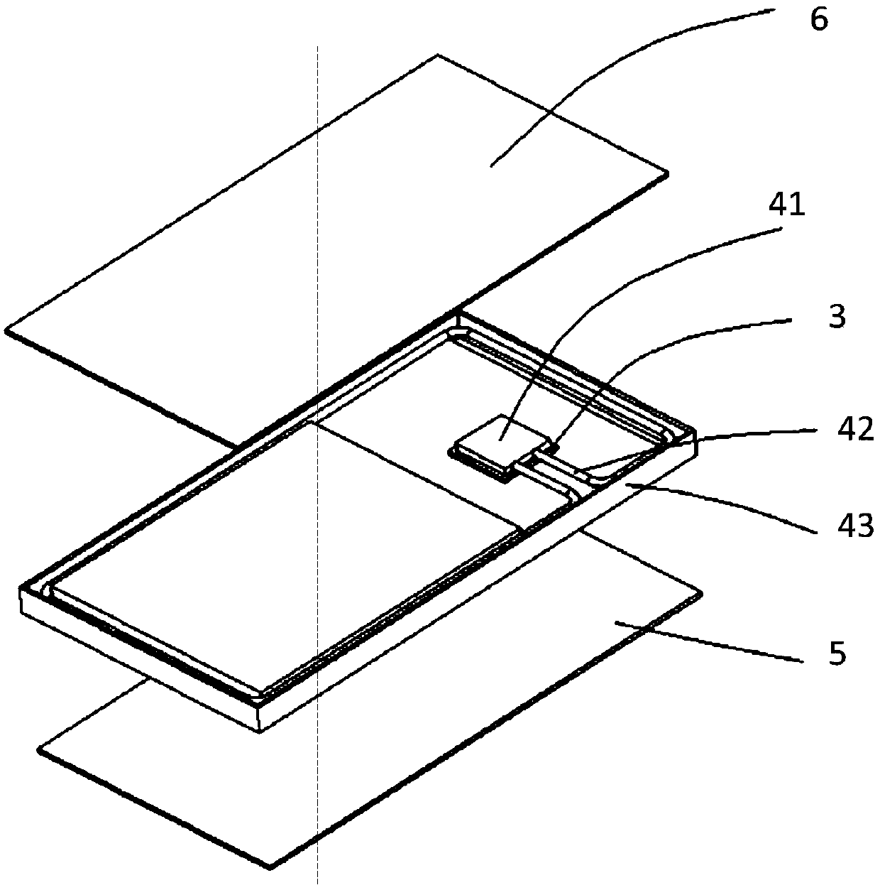
[0021] Such as image 3 with Figure 4 As shown, the heat dissipation structure of the mobile terminal provided by Embodiment 1 of the present invention includes:
[0022] The heat dissipation structure arranged in the housing of the mobile terminal, the liquid heated and vaporized is stored in the heat dissipation structure; the heat dissipation structure includes a transformation chamber 41 and a heat dissipation pipe 42, wherein the transformation chamber 41 is arranged in contact with the heating component 3, and the heat dissipation pipe 42 is connected to the transformation chamber 41 , and form a circuit; the liquid stored in the conversion chamber 41 is heated and vaporized, flows along the heat dissipation pipe 42 in the form of gas, and flows back to the transformation chamber 41 along the heat dissipation pipe 42 in the form of liquid, and the heat dissipation pipe 42 is attached to the frame 43 of the mobile terminal set up.
[0023] Specifically, a conversion ca...
Embodiment 2
[0029] Such as Figure 3 ~ Figure 6 As shown, the heat dissipation structure of the mobile terminal provided by Embodiment 2 of the present invention includes:
[0030] The heat dissipation structure arranged in the housing of the mobile terminal, the heat dissipation structure includes a transformation chamber 41 arranged in contact with the heat-generating component 3 and a heat dissipation pipe 42 connected to the transformation chamber 41 and forming a circuit, the transformation chamber 41 stores heat vaporized liquid; storage The liquid in the conversion chamber 41 is heated and vaporized and flows along the cooling pipe 42 in the form of gas and flows back to the conversion chamber 41 along the cooling pipe 42 in the form of liquid. The cooling pipe 42 is attached to the frame 43 of the mobile terminal.
[0031] Wherein, the conversion chamber 41 includes: an evaporator 410 for vaporizing liquid, a first storage chamber 412 containing the evaporator 410 , and a second s...
Embodiment 3
[0037] Such as Figure 3 ~ Figure 6 As shown, the heat dissipation structure of the mobile terminal provided by Embodiment 3 of the present invention includes:
[0038] The heat dissipation structure arranged in the housing of the mobile terminal, the heat dissipation structure includes a transformation chamber 41 arranged in contact with the heat-generating component 3 and a heat dissipation pipe 42 connected to the transformation chamber 41 and forming a circuit, the transformation chamber 41 stores heat vaporized liquid; storage The liquid in the conversion chamber 41 is heated and vaporized, flows in the form of gas along the heat dissipation pipe 42 and returns to the transformation chamber 41 in the form of liquid along the heat dissipation pipe 42 , and the heat dissipation pipe 42 is attached to the frame 43 of the mobile terminal.
[0039] Wherein, the conversion chamber 41 includes: an evaporator 410 for vaporizing liquid, a first storage chamber 412 containing the e...
PUM
 Abstract
Description
Claims
Application Information
 - R&D
- Intellectual Property
- Life Sciences
- Materials
- Tech Scout
- Unparalleled Data Quality
- Higher Quality Content
- 60% Fewer Hallucinations
Browse by: Latest US Patents, China's latest patents, Technical Efficacy Thesaurus, Application Domain, Technology Topic, Popular Technical Reports.
© 2025 PatSnap. All rights reserved.Legal|Privacy policy|Modern Slavery Act Transparency Statement|Sitemap|About US| Contact US: help@patsnap.com