Housing upper part of labyrinth piston compressor and method for cooling same, and labyrinth piston compressor

A technology for compressors and casings, which is applied to machines/engines, components of pumping devices for elastic fluids, mechanical equipment, etc., can solve the problems of large gap width, leakage, piston wear, etc., and achieve the effect of less leakage

Active Publication Date: 2017-03-22
BURCKHARDT COMPRESSION AG
View PDF5 Cites 2 Cited by
  • Summary
  • Abstract
  • Description
  • Claims
  • Application Information

AI Technical Summary

Problems solved by technology

This labyrinth piston compressor has the disadvantage that wear on one side of the piston may occur, which leads to larger gap widths and more serious leakage

Method used


Image

  • Housing upper part of labyrinth piston compressor and method for cooling same, and labyrinth piston compressor
  • Housing upper part of labyrinth piston compressor and method for cooling same, and labyrinth piston compressor
  • Housing upper part of labyrinth piston compressor and method for cooling same, and labyrinth piston compressor

Examples


Embodiment Construction

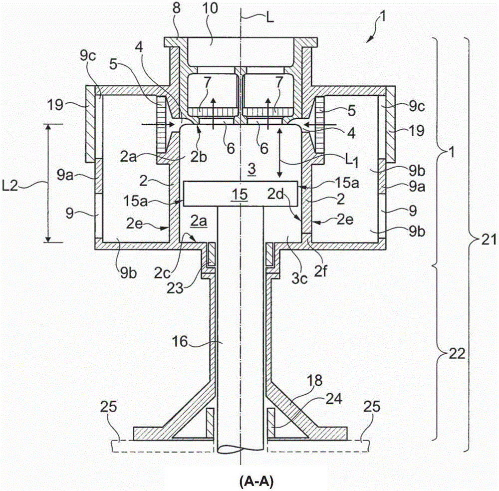
[0029] figure 1 A partial sectional view of a labyrinth piston compressor is shown, which comprises, besides components not shown, a housing upper part 1 , a spacer 22 , a piston 15 with a piston rod 16 , a seal 23 and a linear guide 24 . The housing upper part 1 comprises a cylinder 2 having a cylinder interior 2a extending in the direction of the longitudinal axis L. As shown in FIG. A piston 15 is arranged in the cylinder interior 2 a and is mounted such that it is displaceable together with the piston rod 16 in the direction of the longitudinal axis L in the direction of movement L1 . The piston 15 has, on the peripheral surface forming the side surface 15 a , a thin groove, not specifically shown, extending in the circumferential direction. The cylinder barrel 2 comprises at least one cylinder inlet 4, which opens into the cylinder interior 2a. In addition, a cylinder outlet 6 is provided on the end surface of the cylinder chamber 2a. The cylinder inlet 4 and the cylin...


PUM


Abstract

A housing upper part (1) for a labyrinth piston compressor comprises a cylinder barrel (2) running in the direction of a longitudinal axis (L), with a cylinder interior (2a) and a cylinder barrel exterior (2e), wherein the cylinder barrel (2) has at least one cylinder inlet opening (4, 4a, 4b) or at least one cylinder outlet opening (6, 6a, 6b) which open into the cylinder interior (2a), wherein a gas distribution housing (9a) at least partially encloses the cylinder barrel (2) in the circumferential direction with respect to the longitudinal axis (L) such that there is formed, between the gas distribution housing (9a) and at least one part section (2g) of the cylinder barrel exterior (2e) of the cylinder barrel (2), a gas distribution interior (9b), wherein the part section (2g) is axisymmetric with respect to the longitudinal axis (L), wherein the gas distribution interior (9b) is fluidically connected to the cylinder interior (2a) either via the cylinder inlet opening (4, 4a, 4b) or the cylinder outlet opening (6, 6a, 6b), and wherein the gas distribution housing (9a) comprises either a gas inlet (9) or a gas outlet (10) which is fluidically connected to the gas distribution interior (9b).

Description

technical field [0001] The invention relates to the housing upper part of a labyrinth piston compressor according to the preamble of claim 1 . The invention also relates to a labyrinth piston compressor comprising an upper part of the housing. The invention also relates to a method according to claim 12 for cooling the upper part of the housing of a labyrinth piston compressor. Background technique [0002] A labyrinth piston compressor is a compressor that compresses fluid. In this case, the piston is mounted in the cylinder in such a way that there is a permanent gap between the piston circumference and the cylinder inner wall, so that the piston and the cylinder do not come into contact with each other. At this point it is deliberately tolerated that a portion of the fluid will flow between the cylinder wall and the piston peripheral surface. In order to keep this leakage low, the gap between the cylinder wall and the surrounding surface is kept as small as possible. ...

Claims


Application Information

Patent Timeline
Patent Type & Authority Applications(China)
IPC IPC(8): F04B39/04F04B39/06
CPCF04B39/045F04B39/06F04B39/1046F04B53/162
Inventor U·威林曼恩B·伦博尔德A·艾伦斯帕赫
Owner BURCKHARDT COMPRESSION AG
Why Eureka
Try Eureka