Dumping device

A technology of dumping device and sliding installation, which is applied in the direction of packaging, transportation and packaging, and the type of packaged items, to achieve the effects of saving manpower, easy control of the dumping volume, and a high degree of automation

Active Publication Date: 2017-03-29
安徽旭虹机械设备有限公司
View PDF7 Cites 4 Cited by
  • Summary
  • Abstract
  • Description
  • Claims
  • Application Information

AI Technical Summary

Problems solved by technology

But in reality, how to quantitatively pour the paint into the empty paint bucket has become a big problem that plagues people.

Method used


Image

  • Dumping device
  • Dumping device
  • Dumping device

Examples


Embodiment Construction

[0017] In order to make the technical means, creative features, goals and effects achieved by the present invention easy to understand, the present invention will be further elaborated below.

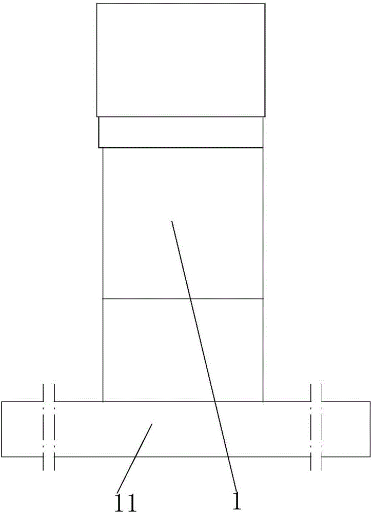
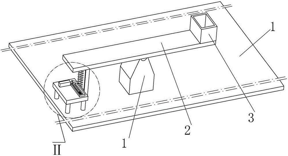
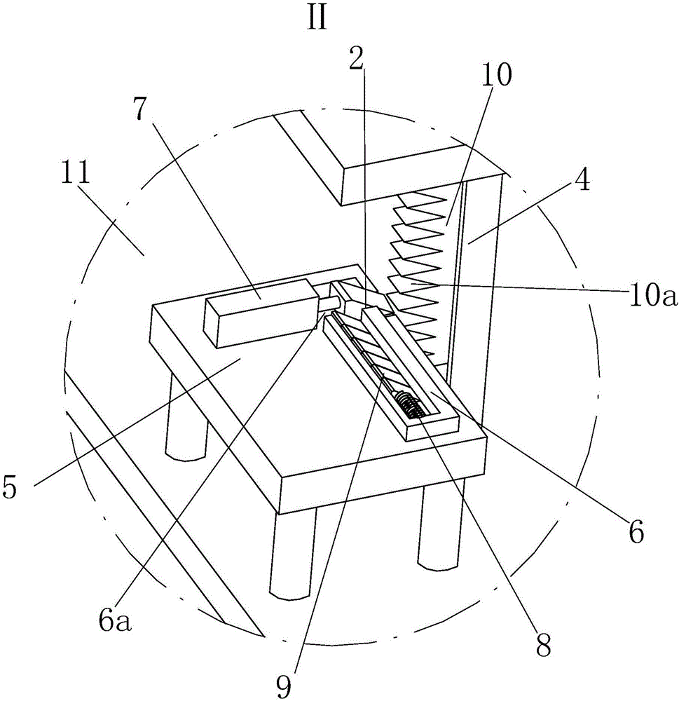
[0018] Such as Figure 1 to Figure 4 As shown, a dumping device includes a general base 11, a top frame 1 is fixedly mounted on the general base 11, a seesaw 2 is hinged on the upper end of the top frame 1, and a storage Box 3, the rear lower end of the seesaw 2 is abutted with a rising push block 10, and the overall base 11 is welded with a guide rail frame 4 that slides and installs the rising push block 10 along the vertical direction, and the rising push block Right triangle calipers 10a are evenly distributed on the rear end face of 10;

[0019] The rear of described rising push block 10 is provided with the pad platform 5 that is fixedly installed on the general base 11, and described pad platform 5 is provided with storage tank rack 6, and the left front end of described tank ra...


PUM


Abstract

The invention relates to a dumping device. The dumping device comprises a total base, a top frame is fixedly arranged on the total base, and a wane is connected to the top frame in a hinged mode; a storing box body is arranged at the upper end of the wine, a rising pushing block is matched with the lower end of the wine in an abutting mode, and a guide rail frame is welded to the total base; right triangle calipers are evenly distributed on the rear end face of the rising pushing block, a base table is arranged behind the rising pushing block, and a storing groove frame is arranged on the base table; openings are formed in the front end and the rear end of the left side of the groove frame correspondingly, a push pressing air cylinder is arranged on the opening closed to the rear side, and a squeezing spring is arranged on the right side in the groove frame; and supporting blocks are squeezingly matched with the left end of the squeezing spring in an abutting mode, the lengths of the bottom of the supporting blocks are larger than the lengths of the right-angle sides of the right triangle calipers, and the oblique planes of the supporting blocks are matched with the oblique planes of the right triangle calipers. According to the dumping device, the supporting blocks and the right triangle calipers are pushed to conduct oblique plane matching on the basis of continuous conveying of the supporting blocks through elastic force of the spring, and the effect that the oblique angle of the automatic controlling storing box body is stably and automatically controlled to dump and contain oil paint is achieved.

Description

technical field [0001] The invention relates to a paint filling process in an assembly line, in particular to a pouring device. Background technique [0002] Paint is not only a kind of paint for home decoration, but also can be applied to the outer layer of metal materials. Generally speaking, after the production of conventional paint, the paint needs to be divided into corresponding paint buckets to facilitate the weighting. And follow-up sales processing. But in practice, how to pour the paint quantitatively into an empty paint bucket has become a big problem that puzzles people. Contents of the invention [0003] Aiming at how to automatically and quantitatively pour the paint into an empty paint bucket when the paint is automatically filled, the present invention proposes a pouring device. [0004] The technical problem to be solved by the present invention adopts the following technical solutions to realize: [0005] A dumping device, comprising a general base, a...

Claims


Application Information

Patent Timeline
Patent Type & Authority Applications(China)
IPC IPC(8): B65B3/04
CPCB65B3/04
Inventor 周玉豹
Owner 安徽旭虹机械设备有限公司
Why Eureka
Try Eureka