

Damping hinge
A technology of damping hinges and hinges, which is applied in the field of hardware, can solve the problems of not being able to freely maintain any included angle, and achieve the effect of wide range and perfect functions
- Summary
- Abstract
- Description
- Claims
- Application Information
AI Technical Summary
Problems solved by technology
Method used
Image

Examples
Embodiment 1
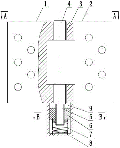
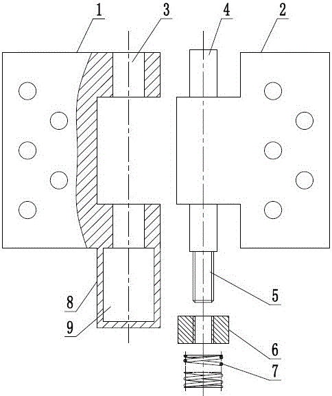
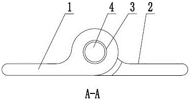
[0026] In embodiment one, if figure 1 , figure 2 , image 3 , Figure 4 As shown, a damping hinge includes a first hinge 1 and a second hinge 2, the first hinge 1 is provided with a mounting hole 3, and the second hinge 2 is provided with a rotating shaft 4, and the rotating shaft 4 can Rotationally installed in the mounting hole 3, the shaft 4 is provided with a screw 5, the first hinge 1 is equipped with a circumferentially fixed nut 6, the screw 5 and the nut 6 form a thread pair, the The nut 6 can slide axially along the rotating shaft 4 , and the first hinge 1 is installed with an elastic member 7 that prevents the nut 6 from sliding. Embodiment 1 The relative rotation of the hinge is converted into the axial movement of the nut 6, and the elastic force of the elastic member 7 on the nut 6 is used to achieve the effect of damping the hinge. On the other hand, the elastic member 7 acts behind the nut 6, and the nut 6 It cannot drive the screw rod 5 and the rotating sh...
Embodiment 2
[0030] In the second embodiment, as shown in 5 , a thrust bearing 10 is provided between the cylindrical spring and the nut 6 . The thrust bearing 10 in the second embodiment can avoid relative sliding between the cylindrical spring and the nut 6, and can make the whole device more stable.
Embodiment 3
[0031] In the third embodiment, as shown in 6, elastic members 7 are installed at both ends of the nut 6 in the limiting hole 9; in the fourth embodiment, as shown in Figure 7 As shown, both ends of the rotating shaft 4 are provided with screw rods 5 , and both ends of the first hinge 1 are respectively provided with accommodating bins 8 , nuts 6 and elastic members 7 . The functions of the third embodiment and the fourth embodiment are the same, and both are for maintaining damping when the first hinge 1 and the second hinge 2 rotate relative to each other in different directions.
PUM
 Abstract
Description
Claims
Application Information