Shifting tool of assembling machine

A machine and tool technology, applied in the field of displacement of assembly and splicing tools, to achieve the effect of improving efficiency and reducing costs

Active Publication Date: 2017-03-29
SHANGHAI ZHENHUA HEAVY IND
View PDF8 Cites 0 Cited by
  • Summary
  • Abstract
  • Description
  • Claims
  • Application Information

AI Technical Summary

Problems solved by technology

The base of the walking roller frame carries the walking roller frame

Method used


Image

  • Shifting tool of assembling machine
  • Shifting tool of assembling machine
  • Shifting tool of assembling machine

Examples


Embodiment Construction

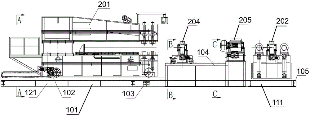
[0017] The invention discloses a displacement tool for a pairing machine, comprising: a base of a pairing machine, a base of a roller group and a base of a walking roller frame. The group-to-machine base carries the group-to-machine. The roller group base carries one or more of the split roller group, the transition roller frame and the hydraulic control station, and the roller group base is connected to the paired machine base. The walking roller frame base carries the walking roller frame.

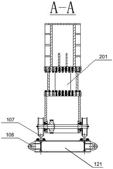
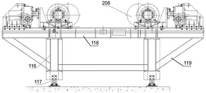
[0018] refer to Figure 1a , Figure 1b , Figure 2a , Figure 2b and Figure 2c , Figure 1a Disclosed is a side structural view of the assembly machine base and the roller set base in the assembly machine shifting tool according to an embodiment of the present invention. Figure 1b Disclosed is a top structural view of the assembly machine base and the roller set base in the assembly machine shifting tool according to an embodiment of the present invention. Figure 2a , Figure ...


PUM


Abstract

The invention discloses a shifting tool of an assembling machine, which comprises an assembling machine base, a roller train base and a walking roller rack base. The assembling machine is supported by the assembling machine base. One or more of a split type roller train, a transition roller rack and a hydraulic control station is/are supported by the roller train base, and the roller train base is interconnected with the assembling machine base. A walking roller rack is supported by the walking roller rack base. The shifting tool of the assembling machine provided by the invention enables the assembling machine to shift flexibly in a whole, the cost is reduced and the utilization efficiency is improved for disassembly is not performed on the assembling machine so that the assembling machine can be directly used after shifting without reinstallation and debugging.

Description

technical field [0001] The invention relates to the field of steel structure processing, and more specifically, relates to the shifting technology of group splicing tools. Background technique [0002] In the manufacturing process of large steel structures, the splicing process of various steel structure components is essential. For example, in the manufacturing process of wind power pipe piles, the pipe bodies of wind power pipe piles are usually manufactured in sections, and then assembled and spliced. The main pairing tool in the process of pairing and splicing is the pairing machine. As a large tool, the assembly machine is installed in the form of a fixed foundation pit, so the position of the assembly machine is fixed and requires a large site. After completing the staged splicing work, if it is necessary to transfer the assembly machine to another working position to continue the assembly process, it is necessary to re-excavate a new foundation pit and backfill the ...

Claims


Application Information

Patent Timeline
Patent Type & Authority Applications(China)
IPC IPC(8): F16M3/00B23K37/04B23K37/00
CPCB23K37/00B23K37/04F16M3/00
Inventor 邹纪祥鞠小刚许金明丁小亮罗鸣
Owner SHANGHAI ZHENHUA HEAVY IND
Why Eureka
Try Eureka