Display and display panel thereof

A technology of display panel and display area, applied in instruments, nonlinear optics, optics, etc., can solve the problem of light leakage in non-effective display areas, and achieve the effect of avoiding light leakage

Active Publication Date: 2017-03-29
TCL CHINA STAR OPTOELECTRONICS TECH CO LTD
View PDF10 Cites 2 Cited by
  • Summary
  • Abstract
  • Description
  • Claims
  • Application Information

AI Technical Summary

Problems solved by technology

The second condition can be satisfied in the effective display area, but since all the signals are transmitted from the non-effective display area to the pixels through metal wires, there are many signals of different voltages, and it is easy to form a voltage difference with the upper substrate, forcing the liquid crystal to rotate, so it is very The effective display area is prone to light leakage

Method used


Image

  • Display and display panel thereof
  • Display and display panel thereof
  • Display and display panel thereof

Examples


Embodiment Construction

[0024] The present invention will be described in detail below in conjunction with the accompanying drawings and embodiments.

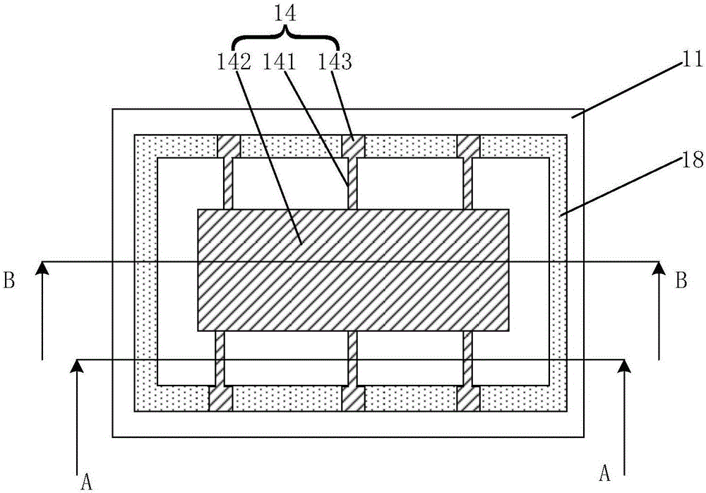
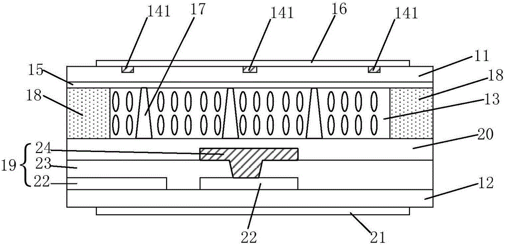
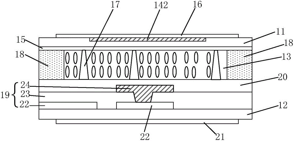
[0025] see figure 1 , figure 2 and image 3 , figure 1 It is a schematic diagram of the distribution of the first transparent electrode layer on the first substrate of the present invention. figure 2 It is the display panel of the present invention along such as figure 1 Schematic cross-sectional view of the A-A direction. image 3 It is the display panel of the present invention along such as figure 1 Schematic cross-sectional view along B-B direction. In this embodiment, the display panel includes a first substrate 11, a second substrate 12, a liquid crystal layer 13 sandwiched between the first substrate 11 and the second substrate 12, and a surface of the first substrate 11 close to the liquid crystal layer 13. The first transparent electrode layer 14 on the first transparent electrode layer 14, the first alignment film 15 arranged on the...


PUM


Abstract

The invention discloses a display panel. The display panel comprises a first substrate, a second substrate, a liquid crystal layer clamped between the first substrate and the second substrate, a first transparent electrode layer arranged on the surface, close to the liquid crystal layer, of the first substrate, a first alignment film arranged on the first transparent electrode layer and a first Polaroid arranged on the surface, away from the liquid crystal layer, of the first substrate; the area of the first Polaroid is greater than that of an effective display area of the display panel; the first alignment film covers the effective display area and a non-effective display area of the display panel; at least part of the first transparent electrode layer is arranged in the non-effective display area in a hollow-out manner. The invention also discloses a display. By means of the mode, light leakage of the display panel can be avoided.

Description

technical field [0001] The invention relates to the field of display technology, in particular to a display and a display panel thereof. Background technique [0002] BPS (Black photo spacer, black support part) technology is a technology that uses black PS. Since the PS material is changed to black, it can play a light-shielding effect, so the functions of BM (black matrix) and PS can be integrated together. In this case, BPS can replace the BM and PS of the original technology at the same time. Thereby saving a process, equipment, materials, greatly saving costs. [0003] BPS technology can be used in liquid crystal display technology, especially in medium-sized and large-sized liquid crystal displays. [0004] Since the BPS material has both the functions of BM and PS, the OD (optical density) value of the unit thickness of the BPS material is not as good as that of the original BM. The peripheral design of the LCD must use BPS material to shield light. Due to the ins...

Claims


Application Information

Patent Timeline
Patent Type & Authority Applications(China)
IPC IPC(8): G02F1/1335G02F1/1337G02F1/1343
CPCG02F1/133528G02F1/1337G02F1/1343
Inventor 叶岩溪
Owner TCL CHINA STAR OPTOELECTRONICS TECH CO LTD
Why Eureka
Try Eureka