
General power flow calculation method of power system provided with UPFC (unified power flow controller)

A power flow calculation and power system technology, applied in flexible AC transmission systems, AC networks with the same frequency from different sources, electrical components, etc., can solve problems such as system calculation difficulties and achieve good convergence characteristics

Active Publication Date: 2017-03-29
STATE GRID JIANGSU ECONOMIC RES INST +2
View PDF3 Cites 15 Cited by
  • Summary
  • Abstract
  • Description
  • Claims
  • Application Information

AI Technical Summary

Problems solved by technology

[0005] The power flow calculation of power systems with similar new UPFC topologies is an essential link in related engineering design. However, the existing power flow calculation methods rarely take this UPFC topology into consideration, and it is still difficult to calculate such systems.

Method used


Image

  • General power flow calculation method of power system provided with UPFC (unified power flow controller)
  • General power flow calculation method of power system provided with UPFC (unified power flow controller)
  • General power flow calculation method of power system provided with UPFC (unified power flow controller)

Examples


Embodiment Construction

[0033] In order to describe the present invention more specifically, the technical solutions of the present invention will be described in detail below in conjunction with the accompanying drawings and specific embodiments.

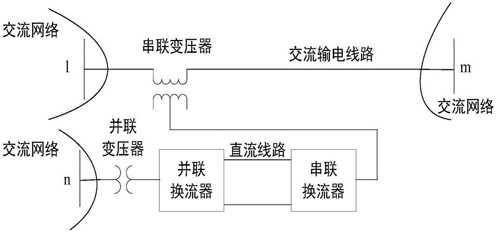
[0034] Figure 1 and figure 2 As shown, the main difference between the traditional topology and the new topology is that the AC bus connected to the UPFC parallel converter in the traditional topology through the parallel transformer is exactly one end of the line connected to the UPFC series side; the new topology does not have this limitation. The same is a new topology, the difference between Figure 1(a) and Figure 1(b) is that the UPFC in Figure 1(a) only contains one series converter and only connects to one series branch; Figure 1(b) contains two A series converter connected to two series branches. The general power flow calculation method of the present invention is applicable to figure 2The traditional UPFC topology shown is also applicable to t...


PUM


Abstract

The invention discloses a general power flow calculation method of a power system provided with a UPFC (unified power flow controller). According to the method, under a premise that the control objective of the UPFC is satisfied, a power injection model and Newton-Raphson method are combined so as to solve the power flow of the power system iteratively. The method is not only suitable for UPFCs of traditional structures, but also suitable to novel UPFCs of which the parallel sides and series sides are connected with different bas-bars or novel UPFCs provided with a plurality of series branches. The present invention also provides specific calculation steps and calculation formulas of power flow calculation. Thus, when the method of the invention is adopted to carry out power flow calculation, new state variables are not needed to be added, the dimensions of Jacobian matrix will not be increased in an iteration process; and the method is easy to implement and has an excellent convergence characteristic.

Description

technical field [0001] The invention belongs to the technical field of flexible power transmission and distribution of power systems, and in particular relates to a general power flow calculation method for power systems containing UPFC. Background technique [0002] my country's power grid is becoming more and more complex, and has developed into a complex and huge system, including various types of power sources, various types of loads, and power transmission and transformation equipment of different voltage levels. In recent years, with the increasing requirements for environmental protection and resource conservation, expanding the scale of the power grid and adding new transmission channels requires huge investment and high costs. How to make full use of existing power generation resources and power transmission and transformation channels has become an increasing concern of the power grid. question. [0003] Flexible AC transmission system (FACTS) technology can great...

Claims


Application Information

Patent Timeline
Patent Type & Authority Applications(China)
IPC IPC(8): H02J3/06G06F17/16
CPCG06F17/16H02J3/06G06F30/367H02J3/1814Y02E40/10G01R21/1331
Inventor 蔡晖谢珍建徐政杨健祁万春张文嘉李辰王荃荃吴晨
Owner STATE GRID JIANGSU ECONOMIC RES INST
Learn More