Reinforced compact fan-shaped section under heavy pressure of continuous-cast solidification tail end

A technology of solidification end and fan-shaped section, which is applied in the field of continuous casting production, can solve the problems such as uncontrollable rebound deformation of cast slab, and achieve the effect of preventing rebound deformation, avoiding looseness, and increasing reduction

Inactive Publication Date: 2017-04-05
NORTHEASTERN UNIV
View PDF7 Cites 7 Cited by
  • Summary
  • Abstract
  • Description
  • Claims
  • Application Information

AI Technical Summary

Problems solved by technology

On the other hand, the single-roll reduction cannot control the rebound deformation of the slab after reduction, and due to the existence of the temperature gradient inside and outside the slab, the thermal shrinkage rate of the core of the slab is significantly higher than that of the slab during the gradual cooling process of the slab. surface, so the core of the slab will continue to produce porosity

Method used


Image

  • Reinforced compact fan-shaped section under heavy pressure of continuous-cast solidification tail end
  • Reinforced compact fan-shaped section under heavy pressure of continuous-cast solidification tail end
  • Reinforced compact fan-shaped section under heavy pressure of continuous-cast solidification tail end

Examples


Embodiment 1

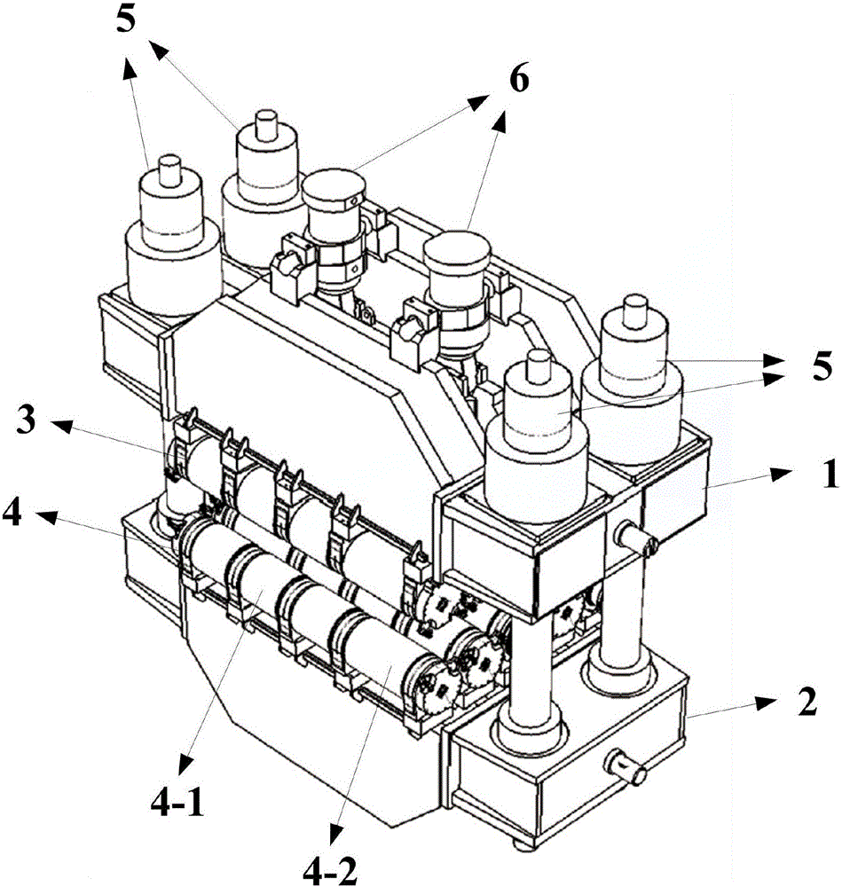
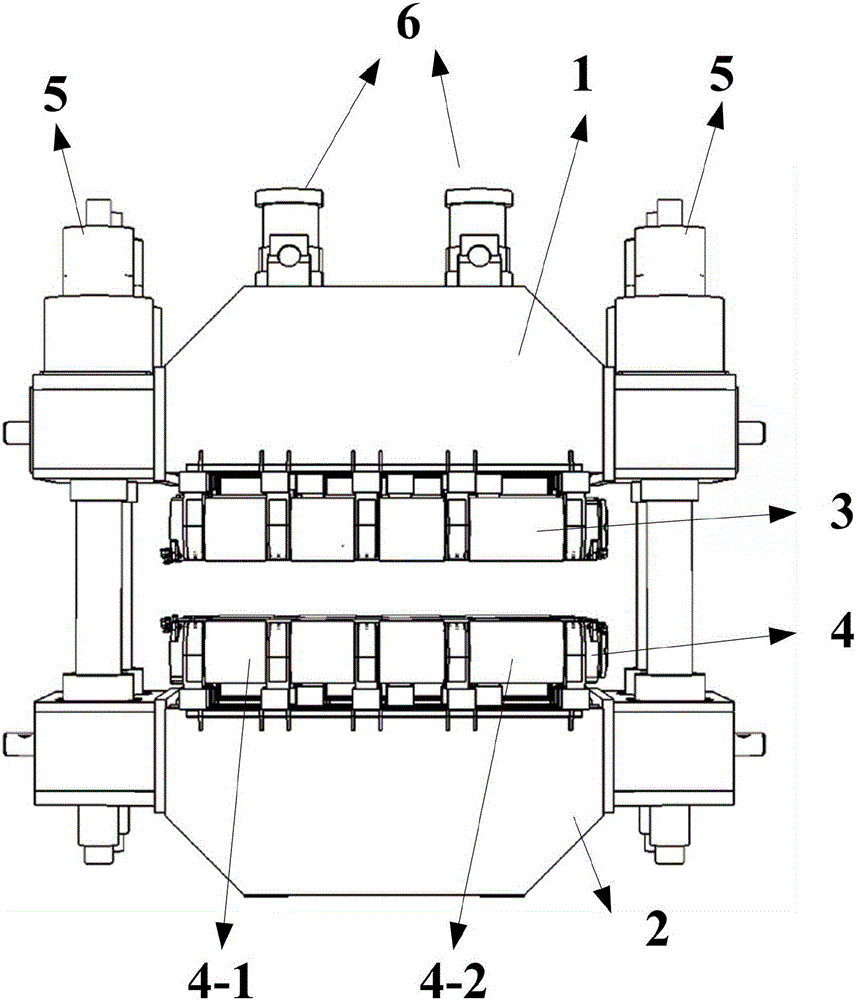
[0026] The invention provides a reinforced compact segment for continuous casting and solidification under heavy pressure, specifically as figure 1 with figure 2 As shown, the fan-shaped section is a horizontal section structure, that is, its roller row is arranged horizontally, including an inner frame 1, an outer frame 2, an inner arc roller row, an outer arc roller row, four clamping cylinders 5 and two Press down the cylinder 6. Wherein, the clamping cylinder 5 is a hydraulic cylinder, which plays the purpose of adjusting the taper of the sector and implementing the process under heavy pressure.

[0027] The inner frame 1 and the outer frame 2 are set up and down oppositely, and the four clamping cylinders 5 pass through the four corners of the inner frame 1 and the outer frame 2 respectively and are fixedly connected with the inner frame 1 and the outer frame 2, and the inner frame 1 and the outer frame of the sector section 2 It has the characteristics of high strengt...

Embodiment 2

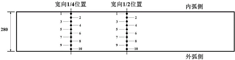
[0038] The cross-sectional size of a wide and thick plate continuous casting machine is 2100mm×280mm, and the horizontal section is composed of 5 compact reinforced fan-shaped sections, namely the 9#-13# section. The segment length is 2.1m, and each segment is composed of 5 pairs of upper and lower rollers. The first upper support roller 3 and the first lower support roller 4 are driving rollers, and the other rollers are driven rollers. The diameter of the driving roller is 390mm. The driving rollers of the inner and outer arc roller rows are equipped with 22kW driving motors at one end, and two pressing cylinders 6 are installed on the driving rollers of the inner arc roller rows. The pressing cylinders 6 are hydraulic cylinders, and the maximum pressure of a single hydraulic cylinder is 1320kN. Four clamping cylinders 5 are installed on the four corners of the inner frame of the segment, and the maximum pressure of a single clamping cylinder 4 is 4750kN. Both the clamping ...


PUM

PropertyMeasurementUnit
Roll diameteraaaaaaaaaa

Abstract

The invention provides a reinforced compact fan-shaped section under heavy pressure of a continuous-cast solidification tail end, and belongs to the field of continuous casting production. The reinforced compact fan-shaped section comprises an inner frame and outer frame oppositely arranged up and down; four clamping cylinders respectively penetrate through four corners of the inner frame and the outer frame; a gap between the inner frame and the outer frame is kept at a set value; an inner arc roller row is connected to the inner frame; an outer arc roller row is connected to the outer frame; the inner arc roller row includes at least more than five upper support rollers; the outer arc roller row includes at least five lower support rollers; the upper support rollers and the lower support rollers adopt sectioned roller structures; at least one of the upper support rollers and the lower support rollers is a driving roller, and the others are driven rollers; one end of the driving roller is connected with a driving motor; and a pressing cylinder is connected with the driving roller in the upper support rollers. The fan-shaped section can prominently increase the pressing quantity of the continuous-cast solidification tail end to prevent the bounce deformation of a cast blank, meanwhile, guarantees synchronous shrinkage of the center part and a blank shell in the internal and external soaking temperature of the cast blank, prevents looseness, and improves the pressing capacity of the solidification tail end.

Description

technical field [0001] The invention belongs to the field of continuous casting production, and in particular relates to a reinforced compact segment for continuous casting solidification end under heavy pressure. Background technique [0002] The soft reduction technology at the end of solidification is an effective means to improve the segregation and porosity of the slab center, and has become a common equipment technology for new continuous casting machines. The light reduction at the solidification end of the bloom is mainly completed by the tension leveler in the air-cooling zone. The reduction of a single roll under the light reduction generally does not exceed 5mm, and the total reduction generally does not exceed 15mm. [0003] However, with the increase of the cross-section of the slab, the penetration efficiency of the reduction to the core of the slab is significantly reduced, and the reduction of the conventional light reduction cannot fully compensate for the s...

Claims


Application Information

Patent Timeline
IPC IPC(8): B22D11/12
CPCB22D11/1206
Inventor 祭程朱苗勇
Owner NORTHEASTERN UNIV
Why Eureka
Try Eureka