
A sector-shaped roll row structure for continuous casting solidification end under heavy pressure and its application method

A technology of solidifying the end and segment, which is applied in the field of continuous casting production, can solve the problems of increasing the size and weight of the segment and difficulty in meeting the process requirements, and achieve the effects of increasing the strain rate, improving the density, and preventing rebound deformation

Active Publication Date: 2020-01-03
NORTHEASTERN UNIV LIAONING
View PDF13 Cites 0 Cited by
  • Summary
  • Abstract
  • Description
  • Claims
  • Application Information

AI Technical Summary

Problems solved by technology

[0005] However, the current design of the heavy-pressed roll row at the end of solidification is difficult to meet the technological requirements of a reduction of more than 15mm. With the increase of the reduction, the strength and rigidity of the roll row should also be greatly improved to ensure the internal quality of the continuous casting slab and Equipment Safety and Reliability
If the diameter of the roll row is increased on the basis of the current heavy-pressed roll row at the end of solidification, the reduction amount of more than 15mm can also be achieved, but the size and weight of the matching fan-shaped section will be greatly increased, which will bring the fan-shaped section. A series of new problems such as hoisting and maintenance

Method used


Image

  • A sector-shaped roll row structure for continuous casting solidification end under heavy pressure and its application method
  • A sector-shaped roll row structure for continuous casting solidification end under heavy pressure and its application method
  • A sector-shaped roll row structure for continuous casting solidification end under heavy pressure and its application method

Examples


Embodiment 1

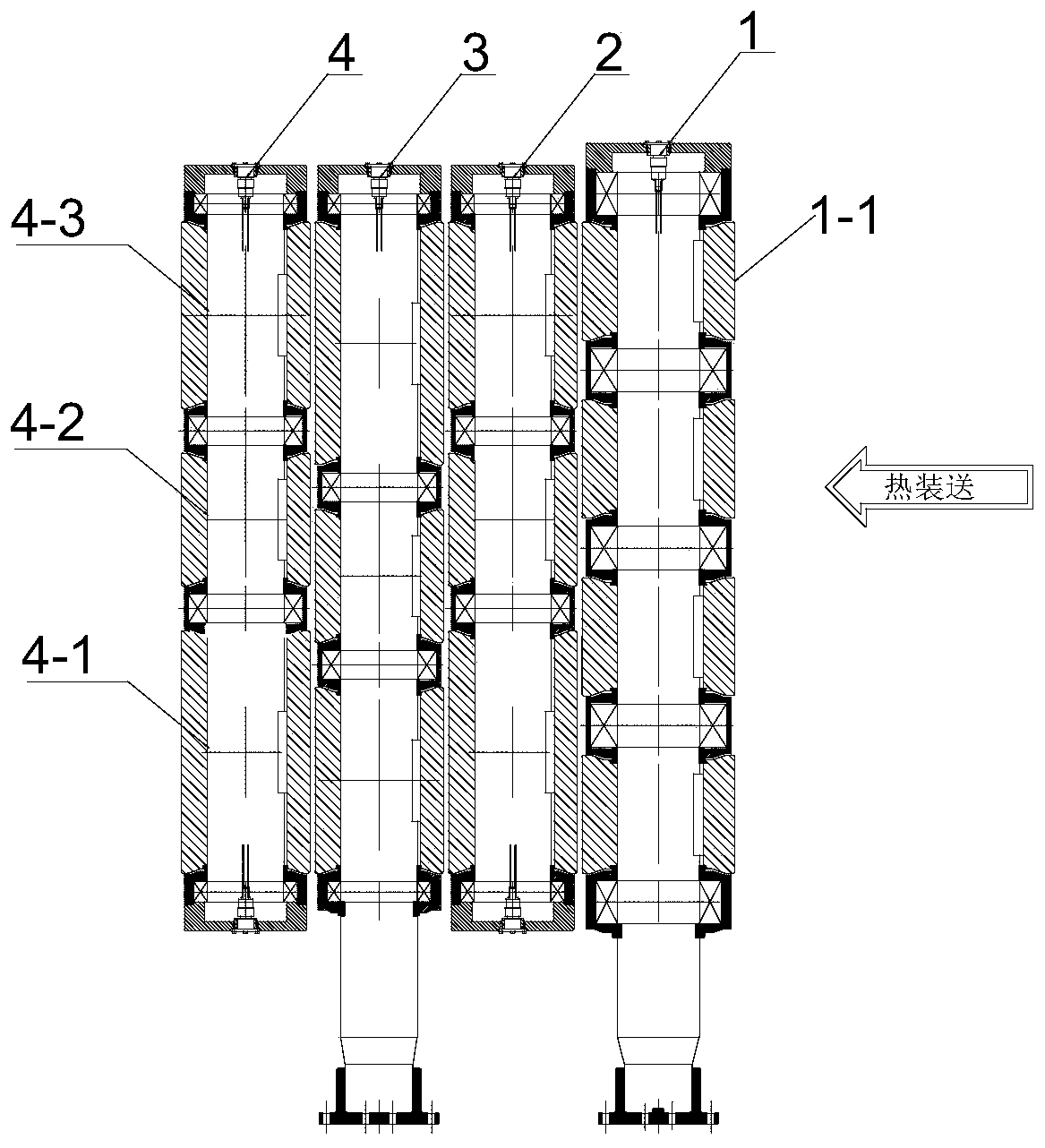
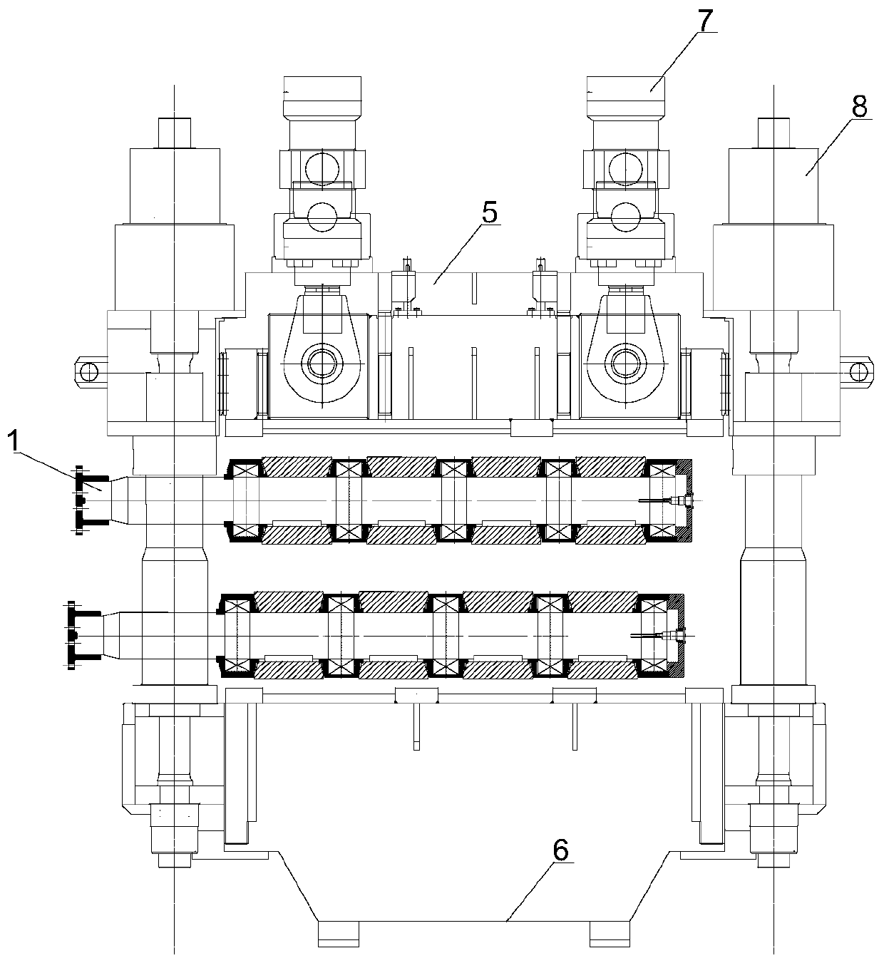
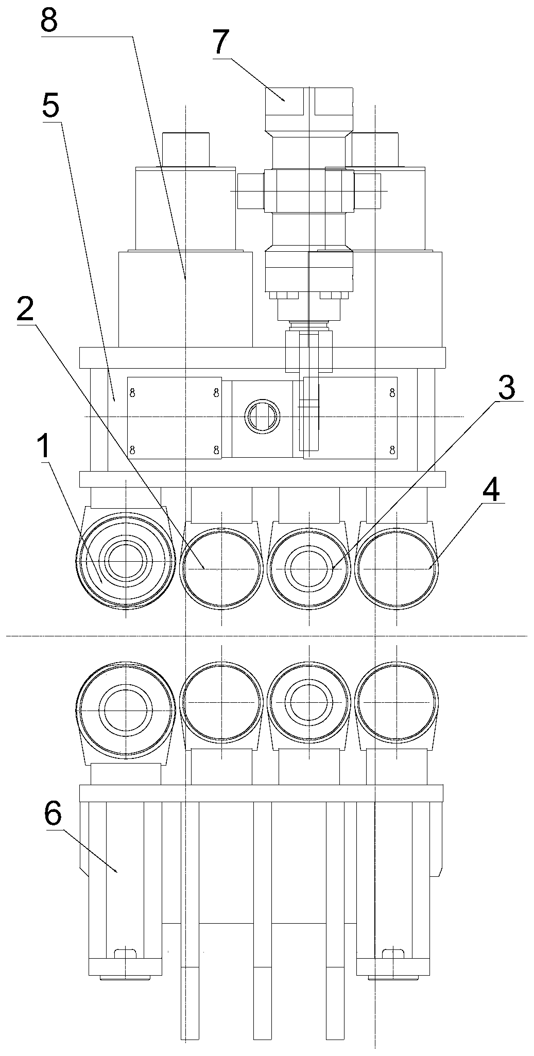
[0027] Such as figure 1 As shown, the present embodiment provides a segmented roller row for heavy pressing at the end of solidification, including four pairs of nip rollers, each pair of nip rollers includes an upper support roller and a lower support roller, and the four pairs of nip rollers are respectively: the first at the entrance A pair of nip rollers 1, and the second pair of nip rollers 2, the third pair of nip rollers 3, and the fourth pair of nip rollers 4 that are arranged in sequence. The first pair of nip rollers 1 is a large-size four-section drive roller, and the second pair of The nip roller 2 and the fourth pair of nip rollers 4 are small-sized three-section driven rollers, and the third pair of nip rollers 3 is a three-section driving roller with the same size as the driven roller.

[0028] Each segmented roller 1-1 of the first pair of nip rollers 1 has the same roll diameter and segment length, and each of the second pair of nip rollers 2 and the fourth pa...


PUM

PropertyMeasurementUnit
forceaaaaaaaaaa

Abstract

The invention belongs to the field of continuous casting production, and specifically relates to a sector-shaped roller row structure and a method of use under heavy pressure at the solidification end of continuous casting. The sector-shaped section roller row has a horizontal section roller row structure, including four pairs of pinch rollers. The first pair of pinch rollers and the third pair of pinch rollers at the entrance of the sector section are driving rollers, and the rest are driven rollers. The diameter of the first pair of pinch rollers is larger than the diameter of the other three pairs of pinch rollers to facilitate the single-point heavy reduction effect. The single-point reduction amount of 3 to 20 mm is implemented on the upper drive roller at the entrance of the sector section, which can effectively increase the center of the cast slab. The strain rate in the central region is conducive to the welding of the central shrinkage cavity and the improvement of the density of the core of the slab. The upper support roller of the third pair of clamp rollers is connected to the hydraulic clamping cylinder to ensure that the slab is continuously pressed and prevents the slab from rebounding and deforming; each subsequent upper support roller in the sector section adopts a reduction rate of 1.0~5.0mm / m to continuously press the slab. , to ensure that the billet does not rebound after being reduced, and at the same time forces the billet shell to continue shrinking, improving the looseness caused by inconsistent shrinkage rates inside and outside the billet.

Description

technical field [0001] The invention belongs to the field of continuous casting production, and in particular relates to a sector-shaped roll row structure and a use method for continuous casting solidification end under heavy pressure. Background technique [0002] With the rapid development of manufacturing industry and science and technology, higher requirements are put forward for the internal quality of steel products. Central porosity and central shrinkage cavity are the main factors restricting the internal quality of continuous casting slabs. Therefore, the solidification end heavy reduction technology is proposed. The heavy reduction technology at the end of continuous casting solidification is to make full use of the characteristics of the large temperature difference between the surface and core of the slab at the end of the slab solidification, and carry out a large deformation reduction on the slab so that the reduction can fully penetrate into the core of the sl...

Claims


Application Information

Patent Timeline
Patent Type & Authority Patents(China)
IPC IPC(8): B22D11/12
CPCB22D11/1206
Inventor 祭程朱苗勇李应焕
Owner NORTHEASTERN UNIV LIAONING
Learn More