Method of repairing a turbine rotor using cold spraying

a turbine rotor and cold spraying technology, applied in the direction of pressure inorganic powder coating, etc., can solve the problems of high strain rate of powder particles, and achieve the effect of high strain rate, high strain rate and high strength

Inactive Publication Date: 2012-11-01
GENERAL ELECTRIC CO
View PDF4 Cites 15 Cited by
  • Summary
  • Abstract
  • Description
  • Claims
  • Application Information

AI Technical Summary

Benefits of technology

[0007]In accordance with an exemplary but nonlimiting embodiment of the invention, either the entire rotor or some parts of the rotor are manufactured by a cold spraying process. Cold spraying is a technique in which dense and well-adhered deposits are formed due to the high velocity impact of powdered feedstock on a substrate. The deposits formed do not undergo phase transformation or oxidation during flight. Moreover, due to high velocity impact, the powder particles undergo high strain at very high strain rates. This leads to grain refinement and a very fine-grained structure in the deposited material. The grain refinement also leads to the formation of nanno-grain structure having a higher strength than materials formed by conventional methods.
[0008]Accordingly, in one aspect, the present invention relates to a method of producing a turbine rotor comprising (a) providing a core shaft; (b) cold spraying alloy powder particles onto the core shaft; (c) controlling the cold spraying to form sections of different shape along the core shaft to thereby form a near-net shape rotor; and (d) treating the near-net shape rotor to relieve stresses and to form diffusion bonding across interfaces between individual powder particles and the core shaft.

Problems solved by technology

Moreover, due to high velocity impact, the powder particles undergo high strain at very high strain rates.

Method used


Image

  • Method of repairing a turbine rotor using cold spraying
  • Method of repairing a turbine rotor using cold spraying
  • Method of repairing a turbine rotor using cold spraying

Examples


Embodiment Construction

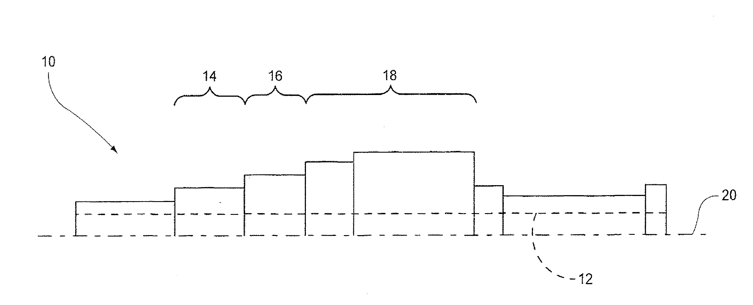
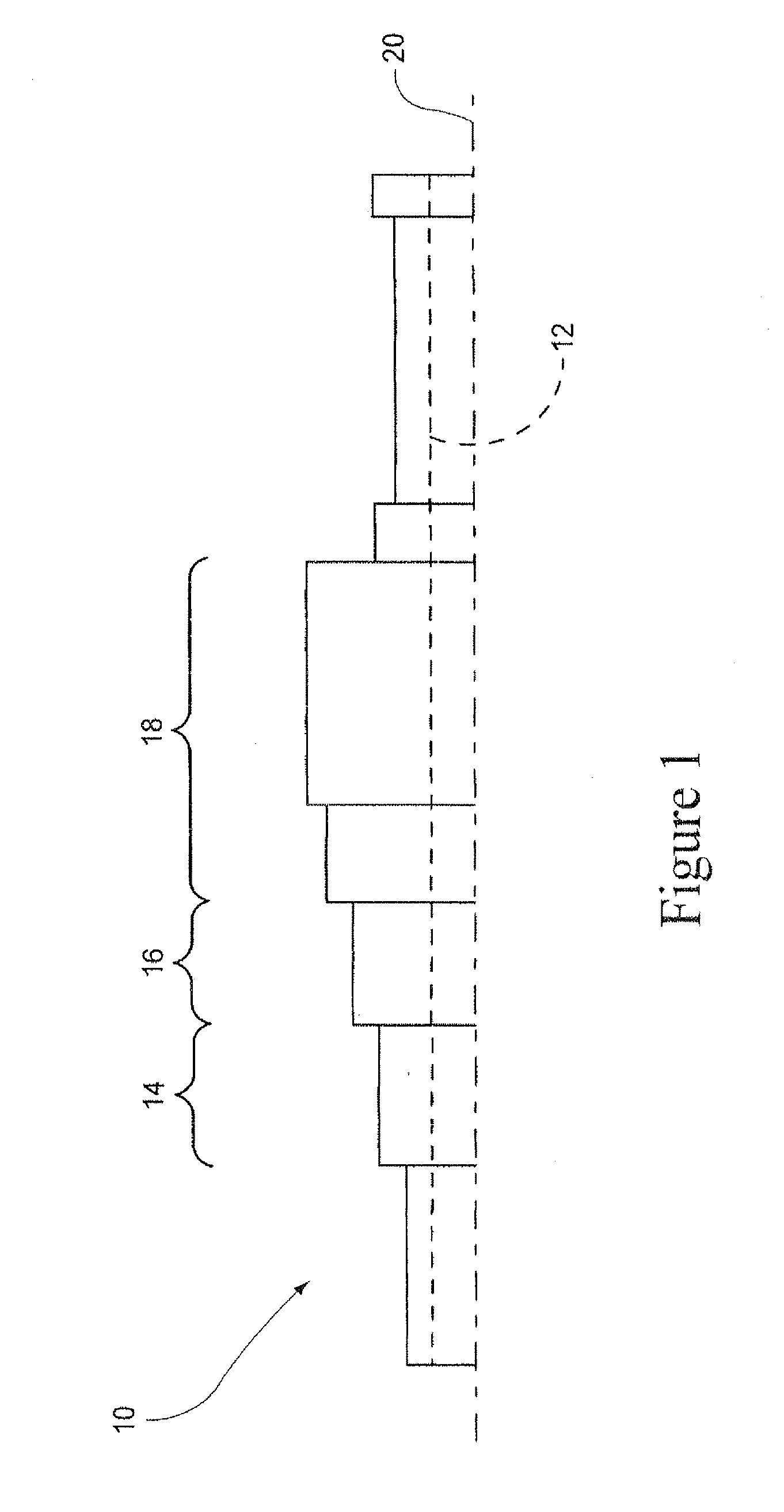
[0014]FIG. 1 shows a partially-formed rotor 10, cold sprayed on a core shaft or mandrel 12. The rotor 10 is shown with built-up portions defining high pressure (HP), intermediate pressure (IP) and low pressure (LP) sections 14, 16, 18, respectively, along a geometric centerline or axis of rotation 20, using a cold-spray process described in further detail below.

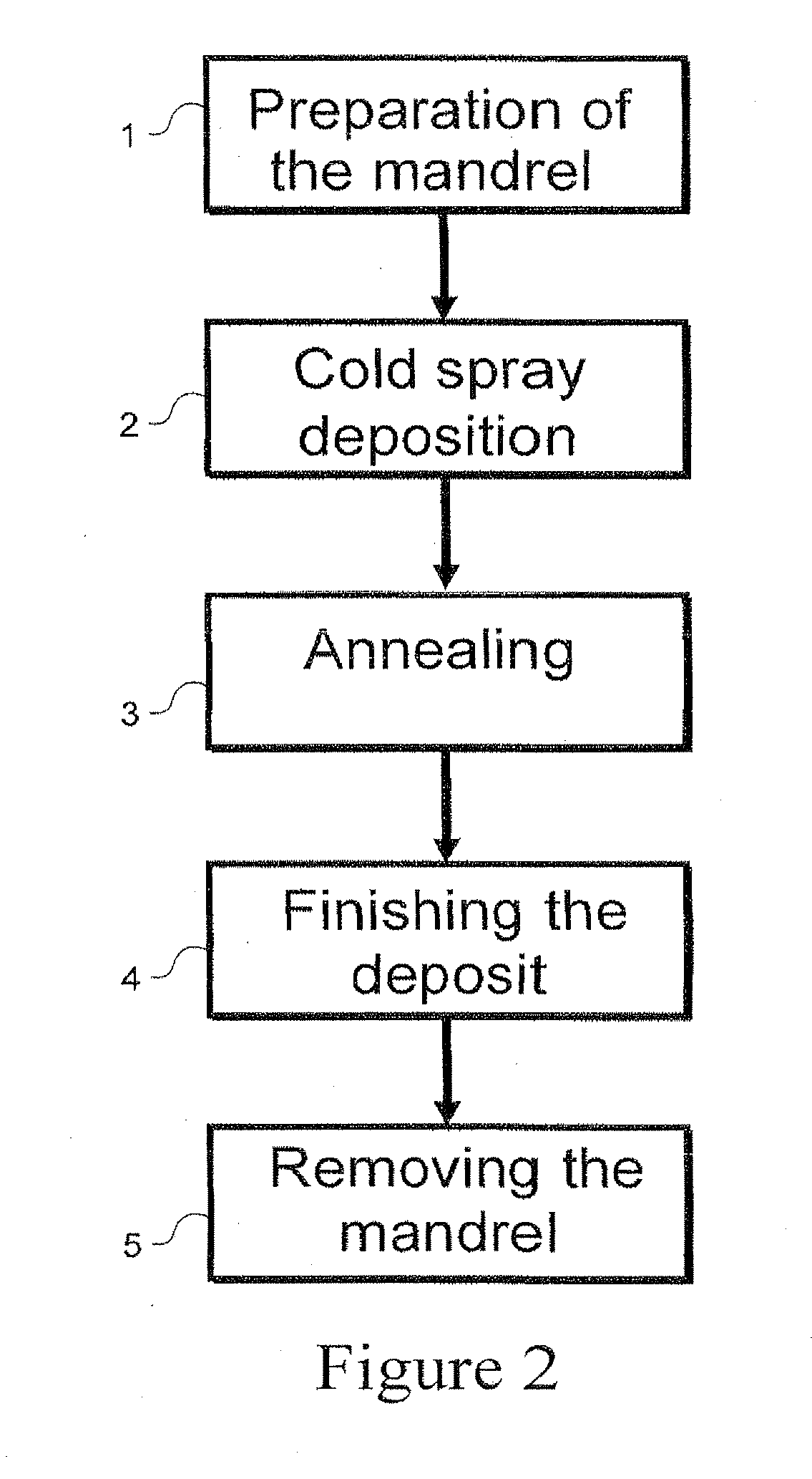
[0015]With reference to the process chart shown in FIG. 2, in a first exemplary but non-limiting embodiment of the invention, the entire rotor 10 is manufactured using primarily an otherwise known cold spraying process. The first step 1 involves preparation of the core shaft or mandrel 12. Specifically, the core shaft or mandrel 12 is cleaned, surface finished and machined to the required profile and shape. For consistency of terminology, a “core shaft” is referred to below in terms of an embodiment where the core shaft remains part of the finished rotor. The core shaft may also be provided, however, in the form of a removabl...


PUM

PropertyMeasurementUnit
standoff distanceaaaaaaaaaa
temperatureaaaaaaaaaa
creep rupture strengthaaaaaaaaaa

Abstract

A method of repairing a damaged rotor comprising: (a) preparing a locally damaged portion of the rotor; (b) cold spraying alloy powder particles onto the locally damaged portion; (c) controlling the cold spraying in step (b) to restore the locally damaged portion to form a repaired portion having substantially the same properties and shape as originally manufactured; and (d) heat treating at least the repaired portion.

Description

[0001]This application is a divisional of U.S. Ser. No. 12 / 574,943, filed Oct. 7, 2009, the entire contents of which are hereby incorporated by reference in this application.BACKGROUND OF THE INVENTION[0002]This invention relates to the manufacture of turbine components and more specifically, to the manufacture of a turbine rotor by a cold spraying process.[0003]Rotors used in the steam turbines, gas turbines and jet engines typically experience a range of operating conditions along their lengths. Different operating conditions complicate the selection of both rotor materials and manufacturing processes for the rotor because materials optimized to satisfy one operating condition may not be optimal for meeting another operating condition. For example, the inlet and exhaust areas of a steam turbine rotor have different material property requirements. The high temperature inlet region typically requires a material with high creep rupture strength but only moderate toughness. The exhaus...

Claims


Application Information

Patent Timeline
Patent Type & Authority Applications(United States)
IPC IPC(8): B23P6/00
CPCB23P15/006Y10T29/4932Y10T29/49012Y10T29/49318Y10T29/49316Y10T29/49325Y10T29/4998C23C24/04B23P6/00
Inventor CALLA, EKLAVYAPABLA, SURINDERGOETZE, RAYMOND
Owner GENERAL ELECTRIC CO
Why Eureka
Try Eureka