Coil discharging device and method of coiling equipment
What is AI technical title?
AI technical title is built by Patsnap AI team. It summarizes the technical point description of the patent document.
A kind of equipment and technology of rewinding reel, applied in the direction of winding strip, transportation and packaging, thin material processing, etc., can solve the problems of long time consumption, low degree of automation, high labor intensity of workers, etc. High degree, saving the effect of unwinding process
Active Publication Date: 2017-04-05
GUANGDONG JINMING MACHINERY
View PDF8 Cites 34 Cited by
Summary
Abstract
Description
Claims
Application Information
AI Technical Summary
This helps you quickly interpret patents by identifying the three key elements:
Problems solved by technology
Method used
Benefits of technology
Problems solved by technology
[0004] The traditional coil unloading and core loading process is mainly carried out manually, with low degree of automation, high labor intensity and long time-consuming
Method used
Image
Click on the blue label to locate the original text in one second.
Reading with bidirectional positioning of images and text.
Examples
Embodiment 1
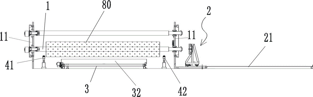
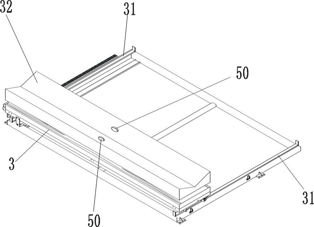
[0062] figure 1 , figure 2 , image 3 , Figure 4 , Figure 5 As shown, the unwinding device of the rewinding device includes an inflatable rewinding shaft 1, the central axis of the rewinding shaft extends laterally, and the left and right ends of the rewinding shaft 1 are installed on the rewinding shaft supports 11 on both sides, and the rewinding shaft supports 11 It is a turntable type rewinding shaft support, and two rewinding shafts can be installed to take turns to rewind and unload; among them, the rewinding shaft support 11 located on the left side is equipped with a rotatable plug 12, and the central axis of the plug 12 rotates with the rewinding shaft 1 The central axis of the winding shaft overlaps, and a plug driving mechanism that drives the plug to rotate is also provided on the left side of the winding shaft bracket 11; the left end of the winding shaft 1 forms a movable plugging relationship with the plug 12, and the plugging direction is The axial direc...
Embodiment 2
[0069] A method for automatically unloading a core, adopting the automatic unloading device of the winding equipment of Embodiment 1, comprising the following steps in sequence:
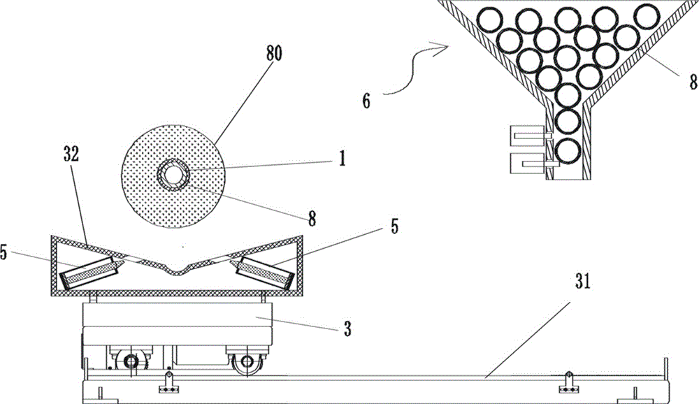
[0070] (1), figure 1 , figure 2 , image 3 , Figure 4 , Figure 5 As shown, when preparing to unload, the rewinding shaft 1 is at the unloading position (in figure 1 , figure 2 , Figure 6 , Figure 7 , Figure 15 , Figure 18 , Figure 19 , Figure 21 , Figure 26 Among them, there are two upper and lower rewinding shafts, among which the unloading state is the lower one); the paper core tube 8 is set outside the rewinding shaft, and the rewinding shaft 1 is in the state of inflation and expansion, and is closely combined with the paper core tube 8 Together, the film roll 80 is wound outside the paper core tube 8, the left end of the winding shaft 1 is inserted into the plug 12, the spline 141 of the plug 12 is inserted into the keyway 142 at the left end of the winding shaft 1, and t...
PUM
Abstract
A coil discharging device of coiling equipment comprises inflation type coiling shafts. A bearing is arranged at the right end of each coiling shaft in a sleeved manner. An annular groove is further formed in the outer surface of the outer ring of each bearing. A clamp strip can be rotationally installed on a coiling shaft support on the right side. An annular flange is further formed at the right end of each coiling shaft. A transverse guide rail extending transversely is further arranged on the right side of a coiling shaft support located on the right side. A core pulling trolley can be transversely and movably installed on the transverse guide rail. Two tongs blocks which are matched pairwise are installed on the left side face of the core pulling trolley. A longitudinal guide rail extending longitudinally is further arranged below the coiling shafts. A carrying trolley capable of carrying film coils is installed on the longitudinal guide rail. A left shaft supporting rolling wheel capable of supporting the coiling shaft is arranged under the left end of the coiling shaft. A right shaft supporting rolling wheel capable of supporting the coiling shaft is further arranged under the right end of the coiling shaft. The invention further provides a coil discharging method of the coiling equipment. By the adoption of the coil discharging device and method of the coiling equipment, the coil discharging procedure can be automatically completed, and the automation degree is high.
Description
technical field [0001] The invention belongs to the technical field of winding in the film production process, and in particular relates to a winding device and a winding unloading method. Background technique [0002] After the film is produced, it needs to be wound around the paper core tube by the winding equipment to become a coil. The outer diameter of the commonly used paper core tube is 96-110mm. During the winding process, the paper core tube is set outside the rewinding shaft, and the paper core tube is driven by the rewinding shaft to rotate continuously, so that the film material is continuously wound up. When the winding reaches the set length and the film roll reaches the set diameter, it is necessary to extract the film roll (together with the paper core) from the winding shaft and transport the film roll to the designated position. This process is called "unloading". After the unloading is completed, a new spare paper core needs to be put on the winding shaf...
Claims
Application Information
Patent Timeline
Application Date:The date an application was filed.
Publication Date:The date a patent or application was officially published.
First Publication Date:The earliest publication date of a patent with the same application number.
Issue Date:Publication date of the patent grant document.
PCT Entry Date:The Entry date of PCT National Phase.
Estimated Expiry Date:The statutory expiry date of a patent right according to the Patent Law, and it is the longest term of protection that the patent right can achieve without the termination of the patent right due to other reasons(Term extension factor has been taken into account ).
Invalid Date:Actual expiry date is based on effective date or publication date of legal transaction data of invalid patent.

