A biofilm denitrification reactor and a method for fast film formation

A reactor and biofilm technology, applied in the field of biofilm denitrification reactor and rapid film formation, can solve the problems of rising dissolved oxygen, affecting the reaction efficiency in anoxic zone, and not considering the removal of total nitrogen, so as to achieve denitrification Nitrogen has a good effect, is conducive to rapid growth, and solves the effect of slow growth and reproduction

Active Publication Date: 2019-03-19
CHINA PETROLEUM & CHEM CORP +1
View PDF11 Cites 0 Cited by
  • Summary
  • Abstract
  • Description
  • Claims
  • Application Information

AI Technical Summary

Problems solved by technology

However, the second aerobic pool of the device is directly connected to the anoxic pool, and the dissolved oxygen in the aerobic pool will be brought into the anoxic pool, and the dissolved oxygen in the anoxic pool will increase, which will affect the reaction in the anoxic area. efficiency
[0005] CN200810012685.6 discloses a quick start-up method for short-range nitrification of ammonia-containing wastewater, which is characterized in that it uses enriched nitrifying bacteria or a mixture of nitrifying bacteria and aerobic activated sludge from sewage treatment plants as the inoculum; although the short-range Rapid start of nitrification, but does not take into account the removal of total nitrogen

Method used


Image

  • A biofilm denitrification reactor and a method for fast film formation
  • A biofilm denitrification reactor and a method for fast film formation
  • A biofilm denitrification reactor and a method for fast film formation

Examples


Embodiment 1

[0035] The sewage to be treated is nitrogenous sewage from a sewage treatment plant, the concentration of ammonia nitrogen is 300mg / L, the concentration of total nitrogen is 500mg / L, the concentration of COD is 400mg / L, and B / C=0.5. Control the pH value of the sewage to 7.0, the treatment temperature is 25°C, add glucose and potassium dihydrogen phosphate to adjust the BOD in the wastewater 5 :N:P=100:5:1.

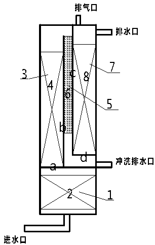
[0036] (1) Put corresponding fillers in the anaerobic zone A1, anaerobic zone A2 and aerobic zone O, so that the volume of the fillers accounts for 3 / 4 of the volume of each reaction zone, and the activated sludge is filled according to the sludge concentration of 5g / L. Sprinkle the mud into the fillers in the three reaction zones; fill the transition zone with sponge iron oxygen scavenger particles, the upper surface of the oxygen scavenger is flush with the upper surface of the vertical plate b, and the volume of the oxygen scavenger accounts for about 3% of the volume o...

Embodiment 2

[0041] The sewage to be treated is nitrogenous sewage from a sewage treatment plant, the concentration of ammonia nitrogen is 300mg / L, the concentration of total nitrogen is 500mg / L, the concentration of COD is 400mg / L, and B / C=0.5. Control the pH value of the sewage to 8.0, the treatment temperature is 35°C, add glucose and potassium dihydrogen phosphate to adjust the BOD in the wastewater 5 :N:P=100:5:1.

[0042] (1) Fill the corresponding filler in the anaerobic zone A1, anaerobic zone A2 and aerobic zone O, so that the volume of the filler accounts for about 3 / 5 of the volume of each reaction zone, and the amount of sludge concentration 10g / L will be activated Sludge is scattered into the fillers in the three reaction zones; the transition zone is filled with sponge iron oxygen scavenger particles, the upper surface of the oxygen scavenger is flush with the upper surface of the vertical plate b, and the volume of the oxygen scavenger accounts for about 10% of the volume of...

Embodiment 3

[0047] The sewage to be treated is nitrogenous sewage from a sewage treatment plant, the concentration of ammonia nitrogen is 300mg / L, the concentration of total nitrogen is 500mg / L, the concentration of COD is 400mg / L, and B / C=0.5. Control the pH value of the sewage to 7.5, the treatment temperature is 30°C, add glucose and potassium dihydrogen phosphate to adjust the BOD in the wastewater 5 :N:P=100:5:1.

[0048] (1) Fill the corresponding filler in the anaerobic zone A1, anaerobic zone A2 and aerobic zone O, so that the volume of the filler accounts for about 3 / 5 of the volume of each reaction zone, and the amount of sludge concentration 7g / L will be activated Sludge is scattered into the fillers in the three reaction zones; the transition zone is filled with sponge iron oxygen scavenger particles, the upper surface of the oxygen scavenger is flush with the upper surface of the vertical plate b, and the volume of the oxygen scavenger accounts for about 10% of the volume of ...


PUM

PropertyMeasurementUnit
particle diameteraaaaaaaaaa

Abstract

The invention discloses a biofilm denitrification reactor and a rapid biofilm forming method. A transverse plate a, a vertical plate b, a vertical plate c and a transverse plate d are arranged in the reactor. The reactor is transversely divided into an upper part and a lower part through the transverse plate a, wherein the lower part is a first anaerobic zone A1, the upper part is longitudinally divided into three parts through the vertical plate b and the vertical plate c, and the three parts sequentially include an aerobic zone O, a transition zone and a second anaerobic zone A2. The lower end of the vertical plate b and the transverse plate a are connected in a sealed manner. A water passing opening is reserved between the upper end of the vertical plate b and the top of the reactor. The upper end of the vertical plate c and the top of the reactor are connected in a sealed manner. A water passing opening is reserved between the lower end of the vertical plate c and the transverse plate a. The left end of the transverse plate d and the bottom of the vertical plate c are connected in a sealed manner. The right end of the transverse plate d and the wall of the reactor are connected in a sealed manner. The transition zone is filled with sponge iron deoxidant particles. When biofilm forming is conducted, water enters the reactor from the bottom, sewage is discharged from the upper portion of the reactor after sequentially passing through the anaerobic zone A1, the aerobic zone O, the transition zone and the anaerobic zone A2, biofilms in all the zones in the reactor are cultivated in a partitioned manner, the biofilms with specific performance can be better formed, the biofilm forming is rapid, and the denitrification effect is good.

Description

technical field [0001] The invention belongs to the technical field of sewage biological treatment, and in particular relates to a biofilm denitrification reactor and a method for quickly forming a film. Background technique [0002] In recent years, with the rapid development of my country's urbanization, my country's water environment pollution and water eutrophication have become more and more serious. More and more seriously hinder the development of our national economy. Nitrogen is the main pollutant that causes eutrophication in water bodies, and it is particularly important to control the total nitrogen content in discharged sewage. [0003] In the biological denitrification process, A 2 The / O biofilm denitrification process is a new biological denitrification process developed rapidly in recent years. This process has the advantages of small tank capacity, difficult sludge expansion, high denitrification efficiency, and convenient operation and management. Tradit...

Claims


Application Information

Patent Timeline
Patent Type & Authority Patents(China)
IPC IPC(8): C02F3/30
Inventor 赵胜楠高会杰孙丹凤郭志华
Owner CHINA PETROLEUM & CHEM CORP
Why Eureka
Try Eureka