
House frame and hollow crossbeam thereof

A beam and hollow technology, applied in the direction of joists, girders, trusses, etc., can solve the problems of poor heat insulation effect and high thermal conductivity of beams, and achieve the effect of maintaining suitable temperature

Inactive Publication Date: 2017-04-05
张引强 +1
View PDF5 Cites 0 Cited by
  • Summary
  • Abstract
  • Description
  • Claims
  • Application Information

AI Technical Summary

Problems solved by technology

[0004] The problem solved by the present invention is that the existing beams used for building frames have high thermal conductivity and poor heat insulation effect, which makes it impossible to maintain a suitable temperature environment in the room for a long time

Method used


Image

  • House frame and hollow crossbeam thereof
  • House frame and hollow crossbeam thereof
  • House frame and hollow crossbeam thereof

Examples


no. 1 example

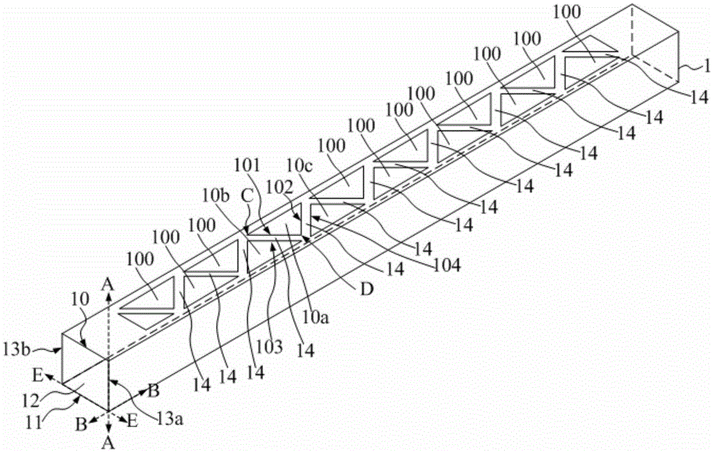
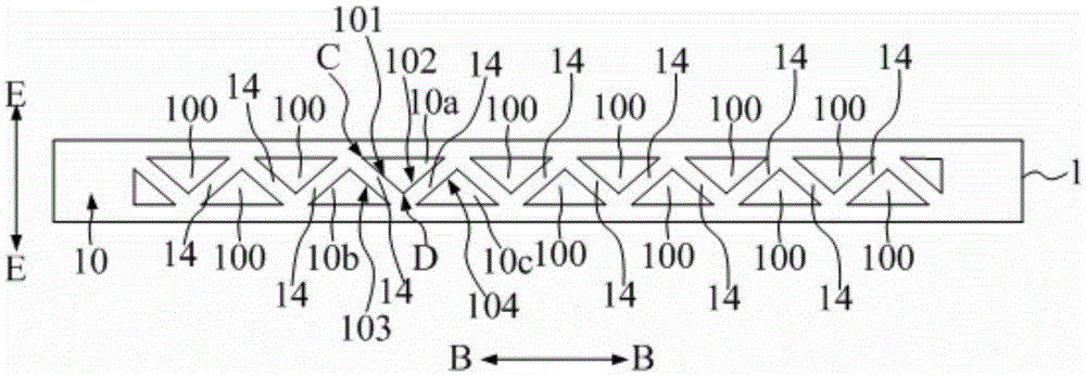
[0026] refer to figure 1 and figure 2 , in this embodiment, the hollow beam 1 includes a top side 10 and a bottom side 11 along the height direction AA of the house, and a number of through holes 100 are distributed in the top side 10 , and the through holes 100 run through the top side 10 .

[0027] Compared with the prior art, this technical solution has the following advantages:

[0028] The through hole 100 reduces the surface area of ​​the top side 10 and the bottom side 11 . When the heat is transferred between the indoor and the outdoor through the top side 10 and the bottom side 11 respectively, the through hole 100 reduces the heat conduction area of ​​the heat on the top side 10, and the heat transfer rate between the indoor and the outdoor is very low. When the outdoor temperature is higher than the indoor temperature, the outdoor high-temperature heat cannot be easily transferred to the indoor, and when the outdoor temperature is low, the indoor room temperature...

no. 2 example

[0043] Compared with the first embodiment, refer to Figure 4 , this example has the following differences:

[0044] In this embodiment, a number of through holes 100' are formed on the bottom edge 11' of the hollow beam 1'. For the shape and distribution of the through holes 100', please refer to the shape and distribution of the through holes in the top edge in the first embodiment. This will not be repeated here.

no. 3 example

[0046] Compared with the first and second embodiments, refer to Figure 5 , this embodiment has the following differences:

[0047] In this embodiment, a number of first through holes 110 are formed in the top edge 10' of the hollow beam 1" and a number of through holes 120 are formed in the bottom edge 11". Regarding the shape and distribution of the first through holes 110, the second through holes For the shape and distribution of the holes 120 , please refer to the shape and distribution of the through holes in the top side in the first embodiment, and will not be repeated here.


PUM


Abstract

The invention relates to a house frame and a hollow crossbeam thereof. The hollow crossbeam comprises a top edge and a bottom edge along the height direction of a house, and a plurality of through holes are distributed in the top edge and / or the bottom edge. A technical scheme adopted in the invention is characterized in that the plurality of through holes are distributed in the top edge and / or the bottom edge of the hollow crossbeam, and the through holes reduce the surface areas of the top edge and the bottom edge. When heat goes through the top surface and the bottom surface and is transmitted between the indoor and the outdoor, the through holes reduce the heat conduction area, so the indoor and outdoor heat conductivity is very low. Outdoor high-temperature heat can not be easily transmitted to the indoor when the outdoor temperature is higher than the indoor temperature, and the indoor temperature cannot be easily lost to the outdoor when the outdoor temperature is low, so the indoor suitable temperature is effectively maintained.

Description

technical field [0001] The invention relates to the technical field of construction, in particular to a house frame and a hollow beam thereof. Background technique [0002] In the existing construction field, a house frame includes several columns and beams connecting the columns, and the beams are usually arranged in the wall of the house frame to form and support the entire wall. [0003] Usually, the overall structure of the beam is integrally formed. The heat conduction area from the indoor to the outdoor direction through the beam is large, and the heat conduction rate between the indoor and the outdoor is relatively large. When the environment is in a low temperature environment, the higher temperature in the room will be lost to the outside of the wall. These factors make it impossible to maintain a suitable temperature environment in the room for a long time. Contents of the invention [0004] The problem to be solved by the present invention is that the existing ...

Claims


Application Information

Patent Timeline
Patent Type & Authority Applications(China)
IPC IPC(8): E04C3/02E04B1/19E04B1/76
Inventor 张引强李艮杰
Owner 张引强
Learn More