
Control message sending method and device

A technology for controlling messages and sending methods. Applied in the field of communication, it can solve problems such as end-to-end deadlocks, no solutions are proposed, and achieve the effect of avoiding deadlocks.

Active Publication Date: 2017-04-05
ZTE CORP
View PDF5 Cites 2 Cited by
  • Summary
  • Abstract
  • Description
  • Claims
  • Application Information

AI Technical Summary

Problems solved by technology

[0018] For the deadlock problem of end-to-end fault transfer in related technologies, no effective solution has been proposed so far

Method used


Image

  • Control message sending method and device
  • Control message sending method and device
  • Control message sending method and device

Examples


Embodiment Construction

[0038] Hereinafter, the present invention will be described in detail with reference to the drawings and examples. It should be noted that, in the case of no conflict, the embodiments in the present application and the features in the embodiments can be combined with each other.

[0039] It should be noted that the terms "first" and "second" in the description and claims of the present invention and the above drawings are used to distinguish similar objects, but not necessarily used to describe a specific sequence or sequence.

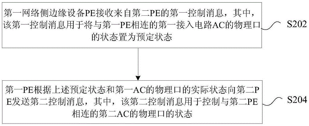
[0040] In this embodiment, a method for sending a control message is provided, figure 2 is a flowchart of a method for sending a control message according to an embodiment of the present invention, such as figure 2 As shown, the process includes the following steps:

[0041] Step S202, the first network-side edge device PE receives a first control message from the second PE, wherein the first control message is used to set the state of the physical...


PUM


Abstract

The invention provides a control message sending method and device. The method comprises the steps that first network side edge equipment PE receives a first control message from a second PE, wherein the first control message is used for setting the state of the physical port of a first access circuit AC connected with the first PE as the preset state; and the first PE sends a second control message to the second PE according to the preset state and the actual state of the physical port of the first AC, wherein the second control message is used for controlling the state of the physical port of a second AC connected with the second PE. With application of the control message sending method and device, the problem of deaklock of end-to-end fault transmission in the relevant technologies can be solved so that the effect of avoiding the problem of deaklock of end-to-end fault transmission can be achieved.

Description

technical field [0001] The present invention relates to the communication field, in particular to a method and device for sending a control message. Background technique [0002] In order to meet the trend of MAN business transformation and triple play integration, network operators tend to use efficient and low-cost packet transport networks to realize multi-service bearer, provide flexible network services, improve network resource utilization, and reduce network deployment complexity. degree, enhance the flexibility of network services, and bring more economic benefits to it. [0003] Layer 2 Virtual Private Network (L2VPN for short) is a technology that relies on Internet service providers and network service providers to establish a private data communication network in a public network. It can be divided into two business models: Virtual Private Lan Service (VPLS for short) and Virtual Leased Line (VLL for short). The former is based on Ethernet service forwarding and...

Claims


Application Information

Patent Timeline
Patent Type & Authority Applications(China)
IPC IPC(8): H04L12/24
CPCH04L41/06
Inventor 杨学成
Owner ZTE CORP
Learn More