Aerial imaging element, aerial imaging display device, and application of aerial imaging display device

An aerial imaging and display device technology, applied in the field of optical imaging, can solve the problems of no real realization, high processing cost, and need to be within tens of nanometers, etc., and achieves the effect of convenient production, reduced safety hazards, and reduced constant and cost.

Active Publication Date: 2017-04-12
FEIXIANG TECH CO LTD +1
View PDF8 Cites 8 Cited by
  • Summary
  • Abstract
  • Description
  • Claims
  • Application Information

AI Technical Summary

Problems solved by technology

[0005] At present, DCRA optical components have been used to realize aerial imaging, but they are limited to the precision requirements of optical components: DCRA optical components are composed of tiny mirrors with a size of 100 μm,

Method used


Image

  • Aerial imaging element, aerial imaging display device, and application of aerial imaging display device
  • Aerial imaging element, aerial imaging display device, and application of aerial imaging display device
  • Aerial imaging element, aerial imaging display device, and application of aerial imaging display device

Examples


Embodiment 1

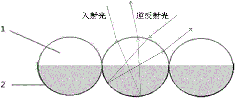
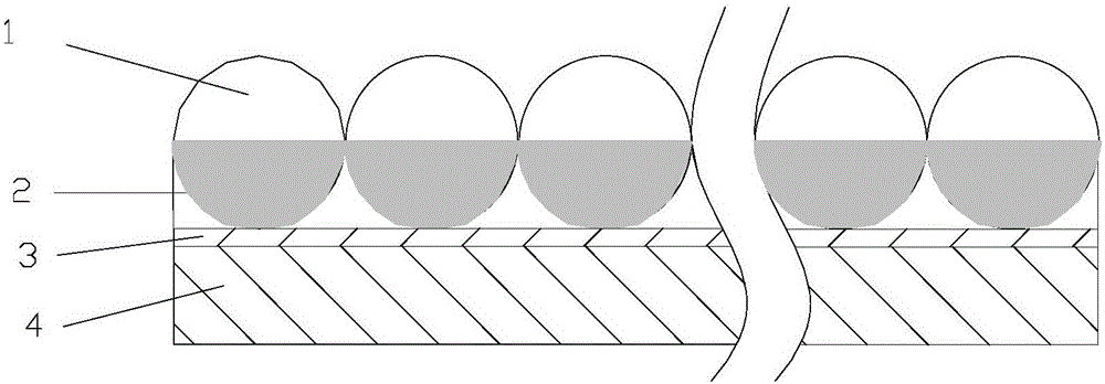
[0053] Such as Figure 1-2 Said, a kind of aerial imaging element, is that the transparent sphere 1 that a plurality of bottoms are coated with reflective film 2 (spherical reflective surface) is neatly arranged on a horizontal plane, and described light passes through the reflective film 2 at the bottom of transparent sphere 1 at least 2 times After reflection, an aerial real image corresponding to the incident image is formed. The diameter of the transparent sphere 1 (that is, the spherical reflective surface 2) is less than 1 mm.

[0054] The transparent sphere 1 is fixed on the cloth surface 4 (or other plate-like objects that can be pasted) through the adhesive layer 3 .

Embodiment 2

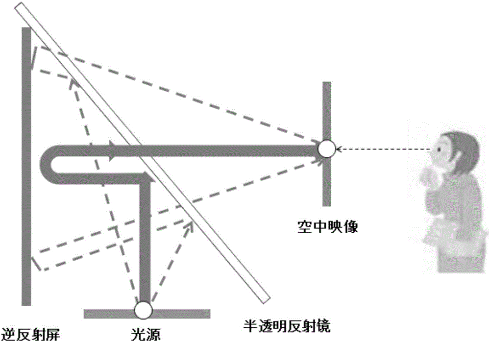
[0056] The aerial imaging display device including the aerial imaging element of Embodiment 1 further includes a projection device for carrying an incident image, and light generated by the incident image displayed by the projection device passes through the aerial imaging element to form a real image in the air. The display device includes a box carrying a projection device, the upper opening of the box is provided with a semi-transparent mirror, and the inner wall of the box is provided with an aerial imaging element (retroreflective screen), such as image 3 shown.

[0057]Preferably, the projection device can perform human-computer interaction in a wired or wireless manner.

Embodiment 3

[0059] Such as Figure 5-6 Shown, a kind of teleprompter comprises main frame and display screen, and main frame is placed on the table 11 that announcer uses (or as Figure 7-8 Below the lectern 14) shown or inside the table, the display screen is located under the table top, the host computer and the display screen are connected, the inside of the table is provided with an aerial imaging element, and the aerial imaging element 12 (or Figure 8 The aerial imaging element 13) in the shown podium is arranged above the display screen, and the light of the text or image displayed on the display screen passes through the aerial imaging element 12 to form a real image R in the air, and the announcer does not need to bow his head and can directly see it.

[0060] Wherein, the air imaging element includes one or more optical elements 1 that bend the light rays of the incident image and form a real image in the air. The optical element is a transparent or translucent sphere coated wit...


PUM

PropertyMeasurementUnit
Diameteraaaaaaaaaa

Abstract

The invention relates to the field of optical imaging, especially an aerial imaging element, an aerial imaging display device, and an application of the aerial imaging display device. In order to solve the above problems, the invention provides an optical element which is simple in structure, is low in production cost, and is suitable for a large-scale aerial imaging display platform. The invention discloses an optical element which enables the light of an incident image to be bent. The bottom section of the optical element is a spherical reflection surface, and the light forms an aerial image corresponding to the incident image after the light is reflected by the reflection surface of the bottom of the optical element at least two times. The application of the aerial imaging technology does not need any medium, and can achieve a real image in the sky without any real object. A person can touch the image through a finger, and also can operate the aerial image, thereby achieving a novel aerial imaging robot interaction system.

Description

technical field [0001] The invention relates to the field of optical imaging, in particular to an aerial imaging element, an aerial imaging display device and applications thereof. Background technique [0002] With the development of science and technology, there are more and more applications of aerial imaging technology. [0003] At present, stereoscopic imaging technology can be divided into three categories: 1) binocular stereoscopic imaging technology, the stereoscopic image is composed of two images with parallax, and the audience needs to wear auxiliary devices to watch, such as binocular viewer, red-green (or red-blue ) glasses, polarizer glasses, liquid crystal light valve glasses, three-dimensional helmet display, etc.; Widely used in multimedia display, advertising display, home decoration, wedding photography, three-dimensional printing and other industries; 3) Laser holographic technology, which requires coherent light to record images, has a wide range of app...

Claims


Application Information

Patent Timeline
IPC IPC(8): G02B5/128G02B27/22G09F19/18
CPCG09F19/18G02B5/128G02B30/56
Inventor 张兵
Owner FEIXIANG TECH CO LTD
Why Eureka
Try Eureka