Composite swinging rod of overturn driving device
A technology of driving device and active swing rod, which is applied to the seat or cover of the toilet, household utensils, sanitary equipment, etc. It can solve the problems of violent impact between the seat cushion and the upper cover, affecting the swing flexibility of the seat cushion, and the seat cushion cannot be fully opened. Achieve the effects of simple assembly, simplified structure and low manufacturing cost
- Summary
- Abstract
- Description
- Claims
- Application Information
AI Technical Summary
Problems solved by technology
Method used
Image
Examples
Embodiment 1
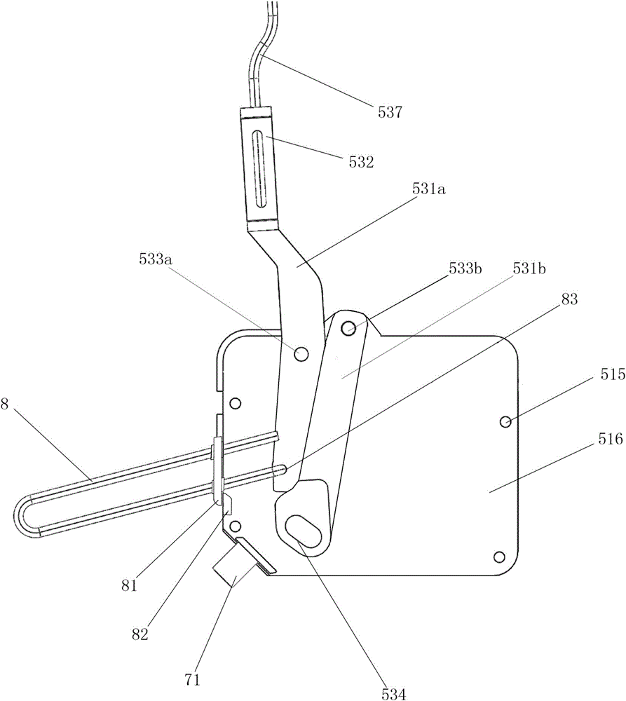
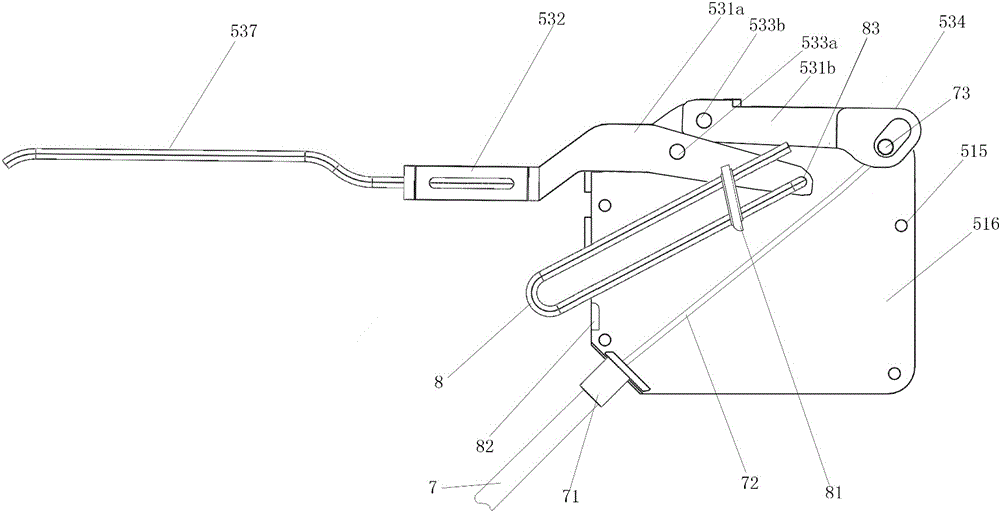
[0022] Embodiment 1: the composite pendulum of the turning drive device shown in the first kind, see figure 1 and figure 2 , including the active swing rod and the driven swing rod. Wherein, the front end of the active swing rod is provided with an end shaft hole, and the rear end is provided with a swing rod traction head. The front end of the driven swing rod is provided with a swing rod front end seat, the middle part is provided with a swing rod central axis hole, and the rear end is matched with the active swing rod.
[0023] The axis hole of the driven swing link and the end axis hole of the active swing link are respectively hinged on the fixed axis one and the fixed axis two of the inner shell. The swing rod traction head is connected with the pedal device through a transmission device. The transmission device is a brake wire and a brake tube, one end of the brake wire is provided with a block, and the other end of the brake wire is fixed on the driving part of the...
Embodiment 2
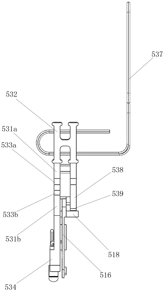
[0025] Embodiment 2: the compound pendulum of the second kind of overturn driving device shown, see image 3 and Figure 4 , on the basis of Embodiment 1, the driven swing rod is a parallel double rod structure, wherein the length of one rod is greater than the length of the other rod; hole, the rear end of the long rod matches and fits the active swing rod, and the rear end of the short rod is located near the central shaft hole of the swing rod and is an arc surface, and the arc surface is concentric with the central shaft hole of the swing rod. The pendulum pulling head is provided with a stopper embedding hole, and a wire slot is arranged in the middle of the stopper embedding hole. A support platform is arranged on the side of the fixed axis one on the inner shell, and the center axis hole of the swing rod is installed on both sides of the fixed axis hole through bearings, while the arc surface of the short rod rear end presses against the surface of the support platform...
Embodiment 3
[0026] Embodiment 3: On the basis of Embodiment 1 or 2, the composite swing rod of the turning drive device shown in the third type is also provided with a lower limit adjustment buffer mechanism or an upper limit adjustment buffer mechanism, and the adjustment buffer mechanism is located in the shell The inner side is provided with an adjustment support, and the hollow area inside the adjustment support is set as a positioning guide groove. The positioning guide groove is matched with a positioning nut so that the adjustment nut can only move axially and cannot rotate. The adjustment screw runs through the inside of the adjustment support and is connected with The positioning nuts are installed together, and a pressure spring is arranged between the outer end surface of the positioning nut and the inner end surface of the positioning guide groove.
PUM
 Abstract
Description
Claims
Application Information
 - R&D
- Intellectual Property
- Life Sciences
- Materials
- Tech Scout
- Unparalleled Data Quality
- Higher Quality Content
- 60% Fewer Hallucinations
Browse by: Latest US Patents, China's latest patents, Technical Efficacy Thesaurus, Application Domain, Technology Topic, Popular Technical Reports.
© 2025 PatSnap. All rights reserved.Legal|Privacy policy|Modern Slavery Act Transparency Statement|Sitemap|About US| Contact US: help@patsnap.com


