Monolithic plate-type swing rod

A plate-type, single-body technology, applied in household appliances, sanitary equipment, applications, etc., can solve the problems of affecting the flexibility of seat cushion swing, violent collision between the seat cushion and the upper cover, and the seat cushion cannot be fully opened, so as to prevent violent impact and simplify assembly. , the effect of structure simplification

Inactive Publication Date: 2017-04-19
郑州勤睿恒电子科技有限公司
View PDF1 Cites 0 Cited by
  • Summary
  • Abstract
  • Description
  • Claims
  • Application Information

AI Technical Summary

Problems solved by technology

However, since the swing rod is always subject to the tension of the brake wire, if the brake wire is not pulled enough, the swing rod cannot stand upright, so the seat cushion cannot be fully opened. If the brake wire stroke is large enough, the foot pressure will easily cause the swing rod to accelerate. (Later, it can be driven with a small force), resulting in a violent impact between the seat cushion and the upper cover
Since the swing rod of the existing turning drive mechanism is integrated, it always affects the flexibility of the seat cushion swing, which needs to be improved

Method used


Image

  • Monolithic plate-type swing rod
  • Monolithic plate-type swing rod
  • Monolithic plate-type swing rod

Examples


Embodiment 1

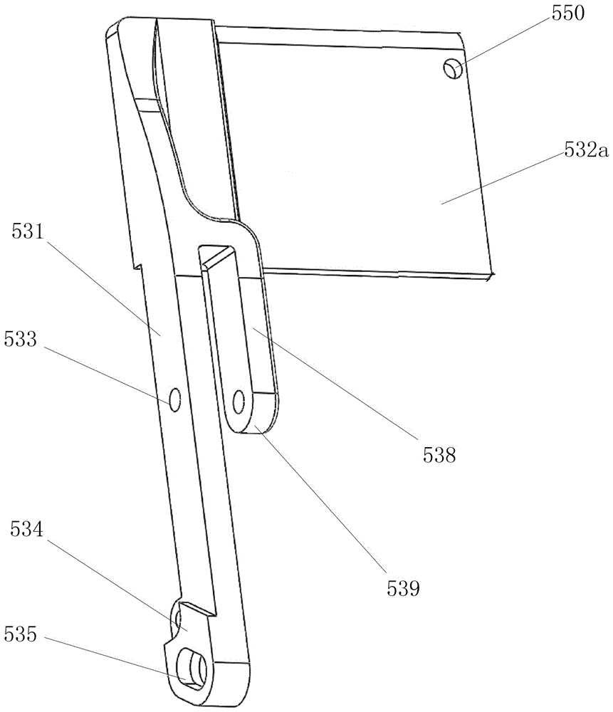
[0023] Embodiment 1: see figure 1 , the first kind of single plate type swing rod, the swing rod is a parallel double rod structure, the length of one rod is longer than the length of the other rod; The middle part of the rod is provided with a swing rod central axis hole, the rear end of the long rod is provided with a swing rod traction head; the short rod rear end is provided with a short rod shaft hole, and the short rod shaft hole is coaxial with the swing rod central shaft hole; The end of the rear end of the short rod is an arc surface, and the arc surface is concentric with the shaft hole of the short rod.

[0024] A spare traction hole is arranged on the transverse plate at the front end of the swing rod, and the spare traction hole is connected with the fixing belt.

[0025] The pendulum pulling head is provided with a stopper embedding hole, and a wire slot is arranged in the middle of the stopper embedding hole.

[0026] The shaft is fixed on the inner shell and ...

Embodiment 2

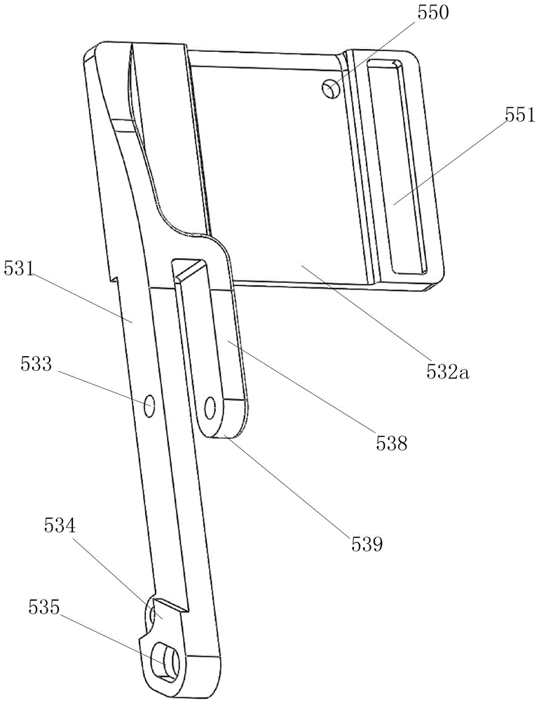
[0028] Example 2: see figure 2 and Figure 4 , the second kind of single plate type swing rod, the side of the front end of the swing rod is provided with a fixing belt sliding hole, and the fixing belt is located in the fixing sliding hole.

Embodiment 3

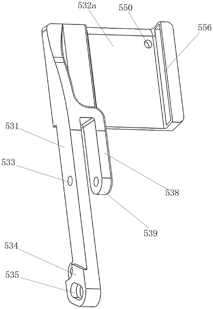
[0029] Embodiment 3: see image 3 , the third one shows the single plate type swing rod, the side of the front end of the swing rod is provided with a positioning chute, the positioning chute is matched with a slider that can only move longitudinally, and the slider is provided with a fixed belt jack, the fixing band is installed in the fixing band jack.

[0030] Explanation: The drawings of the above embodiments are schematic diagrams, and their dimensions do not completely match the outline of the seat cushion. In the case of keeping the overall structural relationship unchanged, the partial dimensions can be adjusted appropriately to make it match the toilet and seat cushion.


PUM


Abstract

The invention discloses a monolithic plate-type swing rod. The monolithic plate-type swing rod is a parallel double rod structure, wherein the front end of a long rod and the front end of a short rod are connected with a transverse slat at the front end of the swing rod at the same time; the middle part of the long rod is provided with a swing rod middle axle hole; the back end of the long rod is provided with a swing rod traction head; the back end of the short rod is provided with a short rod axle hole; the end part of the back end of the short rod is an arc surface; and the arc surface and the short rod axle hole shares the same center of circle. The monolithic plate-type swing rod can adjust the brake cable stroke according to the required cushion gravity and the overturn driving strength of a water closet or can manually control the treading strength. By means of the composite swing rod, the cushion can be flexibly overturned without constraint; no matter the brake cable stroke is in place or no matter the treading strength achieves the maximum degree, as the cushion has movement inertia, the cushion can be lifted automatically. Therefore, the monolithic plate-type swing rod can effectively prevent the cushion bumping the upper cover violently, has a buffer function and can achieve great using effect.

Description

technical field [0001] The invention belongs to the technical field of toilet auxiliary tools, in particular to a device for directly driving a toilet seat cushion to turn over by a pedal connecting rod. Background technique [0002] Toilets exist in every family in the city, and more and more rural users have begun to use toilets. Restrooms in some high-end public places are also equipped with toilets. Ceramic or stainless steel toilets have the advantages of cleanliness, no peculiar smell, convenient use and good comfort, and will gradually replace traditional squatting toilets. [0003] Traditional toilets have always required users to bend down and turn them up and down with their hands, which brings a lot of inconvenience. Whether it is a family or a public place, it is unhygienic to lift the cushion by hand, especially when the finger is lifted, it must touch the bottom of the cushion, and the bottom of the cushion is in direct contact with the upper edge of the toil...

Claims


Application Information

Patent Timeline
IPC IPC(8): A47K13/12A47K13/10A47K13/24
CPCA47K13/12A47K13/10A47K13/24
Inventor 孙明英
Owner 郑州勤睿恒电子科技有限公司
Why Eureka
Try Eureka