Capacity Controlled Rotary Compressor

A rotary compressor and capacity control technology, which is applied in the direction of rotary piston machines, rotary piston pumps, mechanical equipment, etc., can solve the problems of high difficulty in application technology, high cost, and increased reliability of electronic components, and achieve improved Effects of production efficiency, miniaturization of shape, and ease of introduction into industry

Inactive Publication Date: 2011-12-07
GUANGDONG MEIZHI COMPRESSOR
View PDF0 Cites 1 Cited by
  • Summary
  • Abstract
  • Description
  • Claims
  • Application Information

AI Technical Summary

Problems solved by technology

However, this method has the disadvantages of high technical difficulty in application, reliability problems caused by increasing the number of electronic components to be controlled, and high cost.

Method used


Image

  • Capacity Controlled Rotary Compressor
  • Capacity Controlled Rotary Compressor
  • Capacity Controlled Rotary Compressor

Examples


no. 1 example

[0068] Hereinafter, the form of the first embodiment of the present invention will be described based on the drawings.

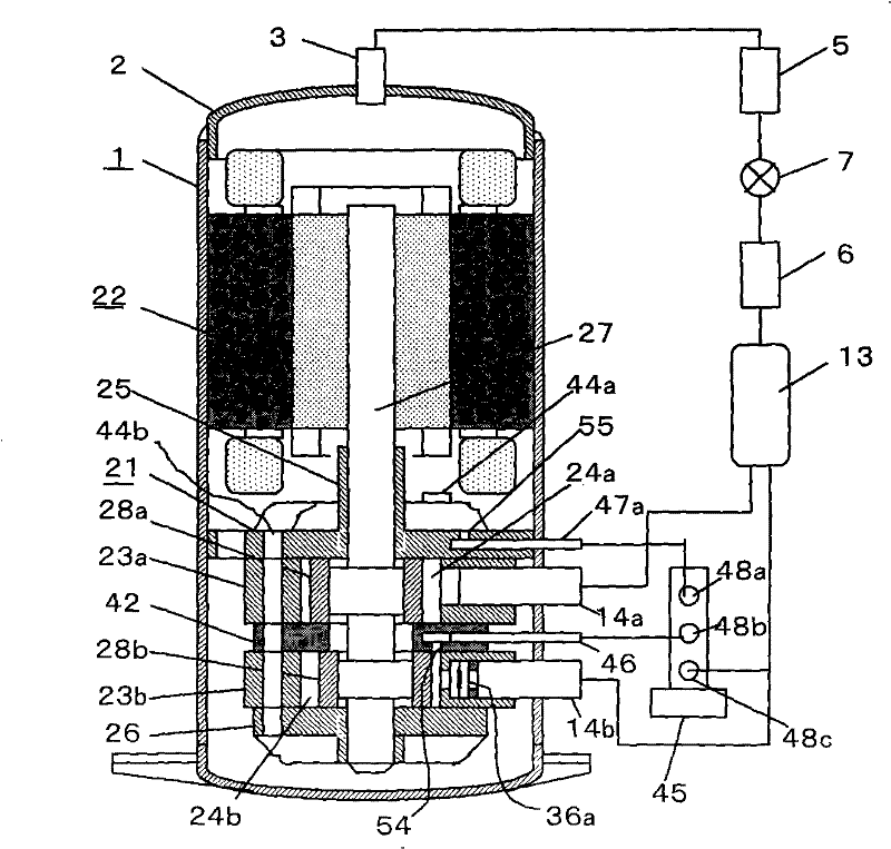
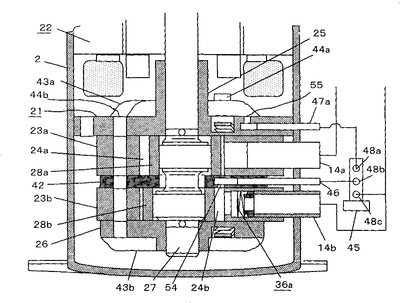
[0069] figure 1 and figure 2 , showing the internal structure of the capacity-controlled rotary compressor and the refrigeration cycle equipped with the compressor. The capacity-controlled rotary compressor is simply referred to as the rotary compressor 1 .

[0070] The rotary compressor 1 is composed of a compression unit 21 installed on the inner diameter of the sealed casing 2 and a motor 22 arranged on the upper part. The compression assembly 21 has two cylinders---the first cylinder 23a and the second cylinder 23b, which are divided by the middle plate 42 to form the first cylinder compression chamber 24a and the second cylinder compression chamber 24b respectively.

[0071] In the first embodiment, the displacement of the second cylinder 23b is small relative to the displacement of the first cylinder 23a. If the sum of the displacements of the two...

no. 2 example

[0104] In the first embodiment, the opening of the first high-pressure output pipe 47a is arranged inside the muffler. In the second embodiment, as Figure 7 As shown, the second high-pressure output pipe 47b is opened inside the sealed casing 2, so the pressure difference Δp between the second high-pressure output pipe and the sealed casing 2 is zero.

[0105] Therefore, it is necessary to carry out a new means of receiving and holding the slide in the slide groove. The pressure switching hole 54 disposed at the tip of the cylinder pressure switching pipe 46 is opened between the second cylinder compression chamber 24b and the first one-way valve device 36a as in the first embodiment.

[0106] In this embodiment, there is still a first one-way valve device 36a, which is arranged at the opening of the second suction pipe 14b located in the compression chamber of the second cylinder, and has nothing to do with the second sliding plate 29b.

[0107] A recess is provided on the ...

no. 3 example

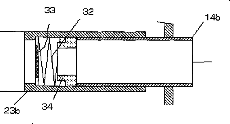
[0115] Such as Figure 9 As shown, the third embodiment, compared with the first embodiment, omits the second suction pipe 14b, and is designed to connect the second check valve device 36b from the first suction pipe 14a to the suction of the first cylinder compression chamber 24a. In the middle of the gas passage, the branch passage 37 of the second cylinder 23b is branched. The second one-way valve device 36b, such as Figure 9 As shown, it is desirable to configure the branch passage 37 designed in the intermediate plate 42 .

[0116] The second one-way valve device 36b consists of the valve seat 34 processed on the branch passage 37, the one-way valve 33, and the coil spring 32 that always presses the one-way valve 33 to the side of the stopper 35 between the two, This is constituted by a stop 35 formed by the planar portion of the second cylinder 23b.

[0117] In the passage from the branch passage 37 to the second cylinder compression chamber 24b, the cylinder pressur...


PUM


Abstract

A capacity-controlled rotary compressor, in which a compression assembly and a motor are arranged in a sealed casing with the internal pressure of the casing as the high-pressure side, and the compression assembly includes a first cylinder, a second cylinder, and an eccentric drive for simultaneously driving the first piston and the second piston The crankshaft, the main bearing and the auxiliary bearing supporting the eccentric crankshaft, and the intermediate plate arranged between the first cylinder and the second cylinder, the first cylinder is provided with the first cylinder compression chamber, the first piston and the first slide slot, The second cylinder is provided with a second cylinder compression chamber, a second piston, and a second slide groove, the first slide is arranged in the first slide groove, the second slide is arranged in the second slide groove, and the gas is sucked The circuits communicate with the compression cavity of the first cylinder and the compression cavity of the second cylinder respectively, and a one-way valve capable of opening and closing the suction gas circuit is arranged in the second cylinder. The invention has the characteristics of being easy to introduce into industry, capable of mass production, and improving production efficiency.

Description

technical field [0001] The invention relates to a rotary compressor, in particular to a capacity control type rotary compressor. Background technique [0002] In recent years, the method of changing the rotation speed of the motor by frequency conversion technology to improve air conditioning capacity control and energy efficiency has become popular. However, this method has the disadvantages of high technical difficulty in application, reliability problems caused by increasing the number of electronic components to be controlled, and high cost. [0003] In order to solve this problem, the research on the capacity control technology of the two-cylinder rotary compressor which is advantageous in terms of ease of application, reliability and cost is advancing. Contents of the invention [0004] The object of the present invention is to provide a capacity-controlled rotary compressor with a simple and reasonable structure, which can improve the air-conditioning capacity cont...

Claims


Application Information

Patent Timeline
Patent Type & Authority Patents(China)
IPC IPC(8): F04C18/356
Inventor 小津政雄李华明
Owner GUANGDONG MEIZHI COMPRESSOR
Why Eureka
Try Eureka